Mimo Receiver Using Lattic Reduction and K-Best Detection

a receiver and lattic reduction technology, applied in the field of wireless communication, can solve the problems of suboptimal detector, loss of performance, and many implementation problems, and achieve the effect of powerful near-ml detection

Inactive Publication Date: 2014-07-03
ST ERICSSON SA
View PDF0 Cites 19 Cited by
  • Summary
  • Abstract
  • Description
  • Claims
  • Application Information

AI Technical Summary

Benefits of technology

[0015]It is an object of the present invention to provide a detection process adapted for a MIMO architecture which achieves powerful near-ML detection.
[0017]It is still a further object of the present invention to provide an effective process which can adapts the complexity to the level of digital processing resources being available in the system.

Problems solved by technology

The SD principle has been introduced and leads to numerous implementation problems.
However, this known technique leads the detector to be sub-optimal because of a loss of performance in comparison with the ML detector.
It is particularly true in the case of an inappropriate K according to the MIMO channel condition number since, unfortunately, it might occur that the ML solution might be excluded from the search tree.
However, although a Neighborhood study remains the one and only solution that achieves near-ML performance, it may lead to the use of a large size Neighborhood scan that would correspond to a dramatic increase of the computational complexity.
A computational complexity reduction by considering the correlation between adjacent-channel is not possible, even if the channel may be considered as constant over a certain block code size within the coherence band (time).
However, the offered performance has been shown to be near-ML, but at the price of a large computational complexity in the QPSK case.

Method used


Image

  • Mimo Receiver Using Lattic Reduction and K-Best Detection
  • Mimo Receiver Using Lattic Reduction and K-Best Detection
  • Mimo Receiver Using Lattic Reduction and K-Best Detection

Examples


first embodiment

1) First Embodiment

[0107]One will now describe with respect to FIG. 9 one first embodiment of a process for carrying out a detection in the Original Domain Neighborhood (ODN), based on a Lattice Reduction aided (LRA) MMSE detection, involving the different functional blocks of FIGS. 2-8.

[0108]As described above, the particular embodiment successively involves a preprocessing phase (A)—only depending on the channel —, then followed by an loading phase (B) for processing the received observations and then completed by a phase of neighborhood search (C) within the Original Domain Neighborhood (ODN) for the purpose of achieving the detection.

A. Preprocessing

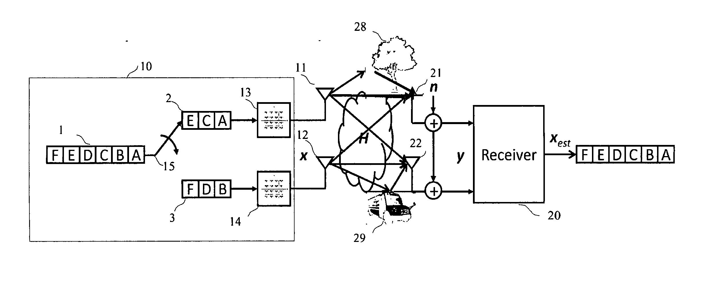
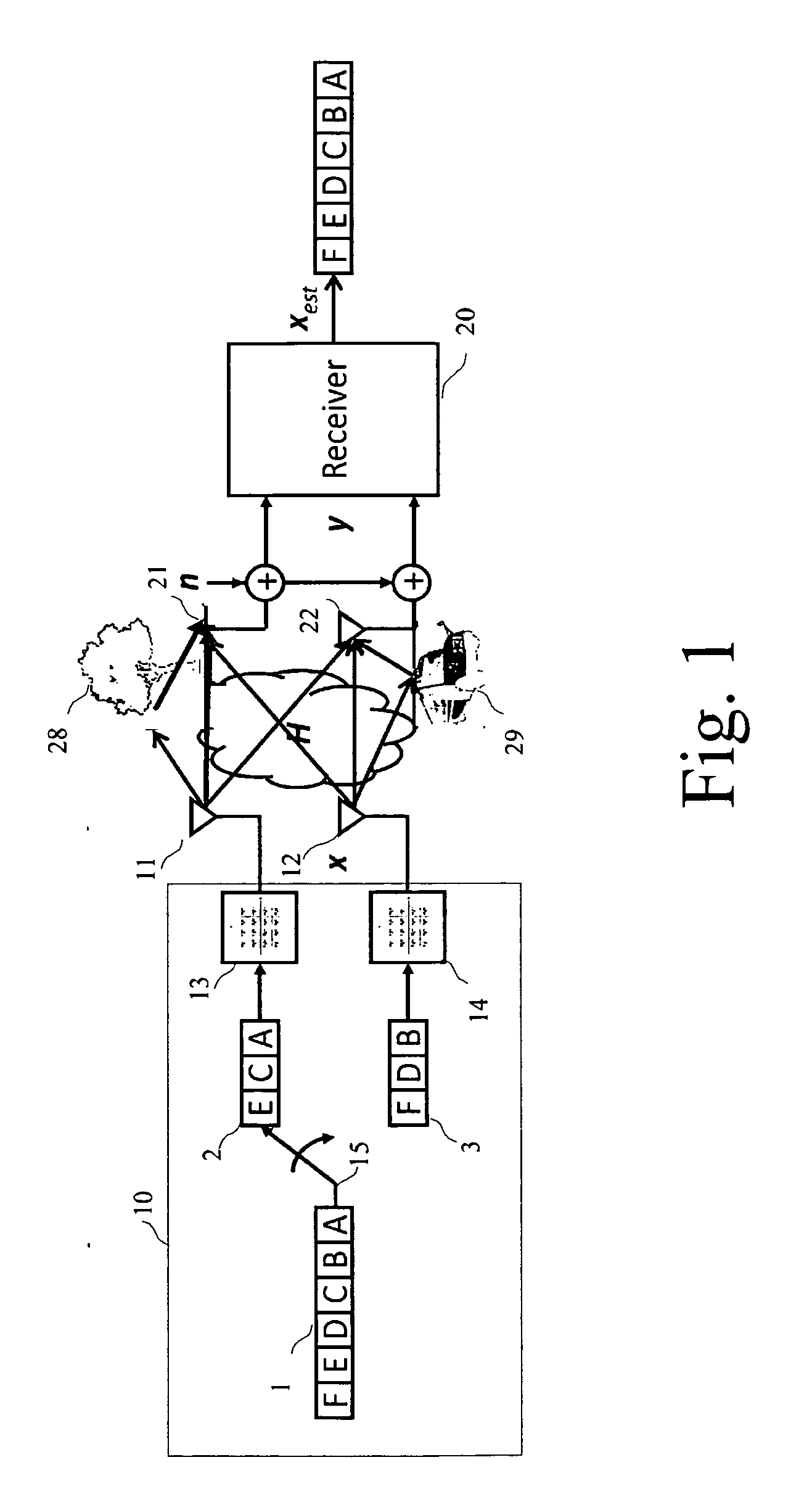
[0109]The preprocessing phase starts with the assumption of the knowledge of the channel H which can be determined by any conventional means, such as for instance by the use of pilot or reference signals.

[0110]Also, it is assumed that the variance of the noise (σ2) is known.

[0111]Such parameters may be determined, for instance, after...

second embodiment

2) Second Embodiment

[0139]With respect to FIG. 10, there will now be described how the two RDN and ODN mechanisms can be combined for the purpose of achieving a highly effective detection process which takes into account the level of resources available in the receiver.

[0140]A. Preprocessing Phase

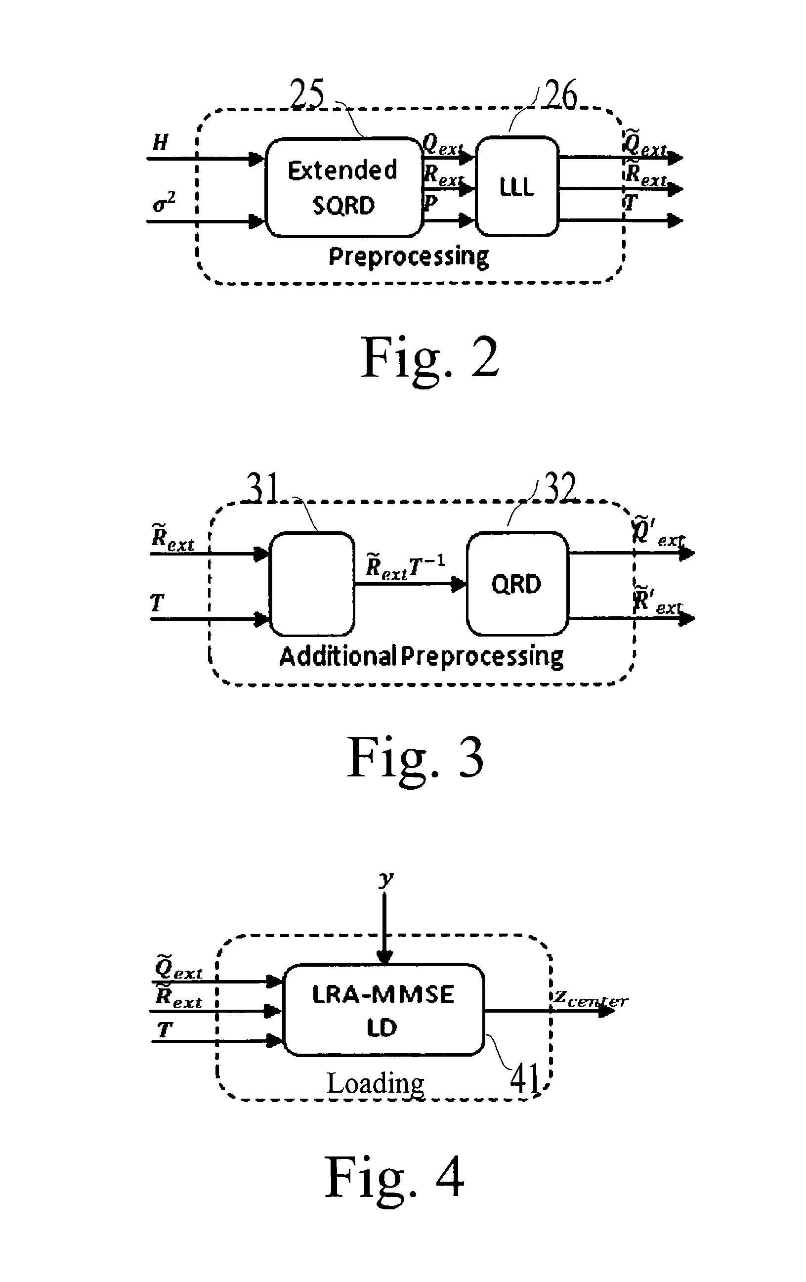
[0141]The process starts with a step 71 consisting in the first QRD decomposition which was described in reference to step 61 of FIG. 9, yielding the three parameters: Qext, Rext, and P.

[0142]Then, in a step 72, the process applies, similarly to the step 62, a lattice reduction in order to generate the following matrices {tilde over (Q)}ext, {tilde over (R)}ext, T and T−1 with T being a transformation matrix which takes into account the permutations already accounted with matrix P, plus the additional changes resulting from the lattice reduction.

[0143]Then a test is performed in a step 73 for the purpose of determining whether the level of digital resources is superior to a predetermined le...


PUM


Abstract

A detection process for a receiver of a wireless communication system based on Multiple-Input Multiple-Output antennas (nT, nR), said receiver processing observations symbols y derived from symbols x transmitted by an emitter through a channel H; characterized in that it involves: —a preprocessing which only depends on the channel H, said preprocessing involving: —a first QRD decomposition (61) for the purpose of decomposing said channel H into two Qext and Rext matrices, with QextHQext= / and Rext being upper triangular; —a lattice reduction (62) for the purpose of generating Qext, Rext and a transformation matrix T; —a second QRD decomposition (63) applied on the matrix Rext T−1 for the purpose of generating two matrixes Q′ext and R′ext, —a loading phase (64, 65, 66) comprising a linear detection process of the observations y for the purpose of generating a value xcenter; —a neighborhood search (67-70) performed in the Original Domain Neighborhood (ODN) with a search center being equal to the result xcenter of said loading phase, said neighborhood search determining a limited number of symbols (K-best).

Description

TECHNICAL FIELD[0001]The invention relates to the field of wireless communication and more particularly to a process for performing near-ML detection in a receiver of a wireless MIMO communication system.BACKGROUND ART[0002]Wireless communication based on multiple antennas is a very promising technique which is subject to extensive investigations so as to take into advantage of the significant increase of data rate which may be obtained by such technique.[0003]FIG. 1 illustrates a basic 2×2 multiple-Input Multiple Output (MIMO) spatial multiplexing communication between an emitter 10 and a receiver 20, and the processing of a single data flow represented by reference 1 which is divided into two distinctive data streams 2 and 3 by means of a multiplexer 15 and each subflows are then being processed by a respective modulator and RF circuit (resp. 13 and 14) before being conveyed to two transmit antennas 11 and 12.[0004]On the receiver side, two antennas 21 and 22 provides two RF signa...

Claims


Application Information

Patent Timeline
Patent Type & Authority Applications(United States)
IPC IPC(8): H04L27/26
CPCH04L27/2649H04L25/0246H04L25/03216H04L25/03242H04B7/0697H04L25/03968
Inventor AUBERT, SEBASTIEN
Owner ST ERICSSON SA
Why Eureka
Try Eureka