Fan assembly

a technology of fan assembly and fan body, which is applied in the direction of space heating and ventilation details, gas purification by non-gaseous materials condensation, and domestic heating details, etc. it can solve the problems of mist emission into the environment, achieve the effect of facilitating cleaning of internal surfaces, increasing the volume of stored water, and increasing the rate of reducing the number of bacteria

Active Publication Date: 2014-07-31
DYSON TECH LTD
View PDF6 Cites 46 Cited by
  • Summary
  • Abstract
  • Description
  • Claims
  • Application Information

AI Technical Summary

Benefits of technology

[0028]The humidifying apparatus preferably comprises a base upon which the water tank is mounted. The base preferably comprises the chamber, the air flow generating means and the inlet duct, with the water tank comprising the outlet duct. The chamber preferably forms part of a water reservoir connected to the base. The water reservoir preferably comprises an inlet chamber for receiving water from the water tank, and for conveying water to said chamber. Part of the outlet duct is preferably removable from the water tank to facilitate cleaning of the internal surfaces of the outlet duct.
[0029]The atomizing means preferably comprises a transducer. The humidifying apparatus preferably comprises control means for controlling the irradiating means and the frequency of vibration of the transducer. The control means is preferably arranged to actuate at least one of the irradiating means and the air flow generating means prior to actuation of the transducer. During the period of time in which the irradiation is performed prior to the atomization of stored water, the water stored in the chamber is agitated to generate a flow or swirl of water within the chamber, and which conveys water through the UV radiation emitted into the outlet section of the chamber. This can increase the volume of the stored water which is irradiated with UV radiation prior to the atomization of the stored water, and thus increase the rate of reduction of the number of bacteria within the water stored in the chamber.

Problems solved by technology

The water droplets enter the flow of air passing through the air duct, resulting in the emission of a mist into the environment.

Method used


Image

  • Fan assembly
  • Fan assembly
  • Fan assembly

Examples


Embodiment Construction

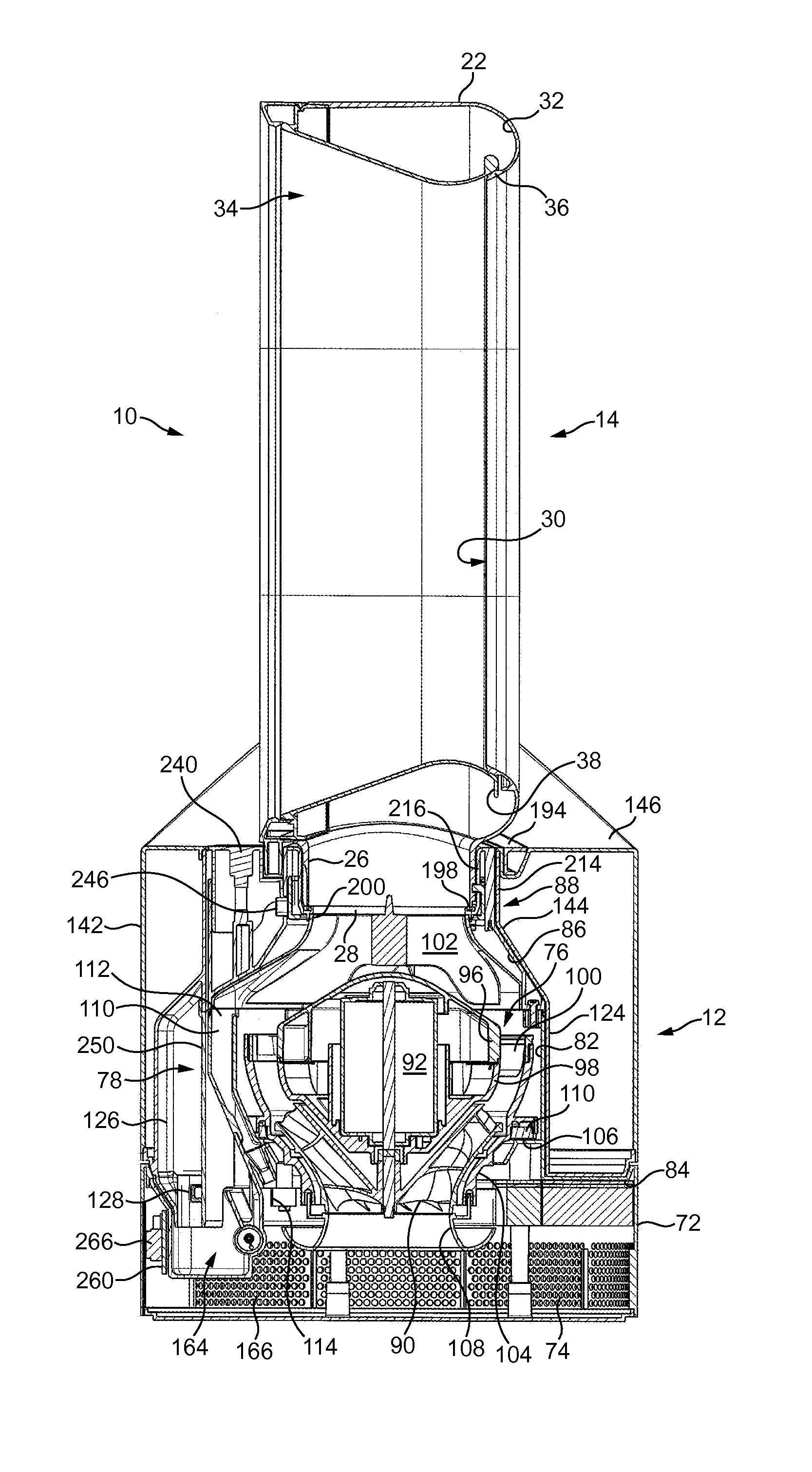
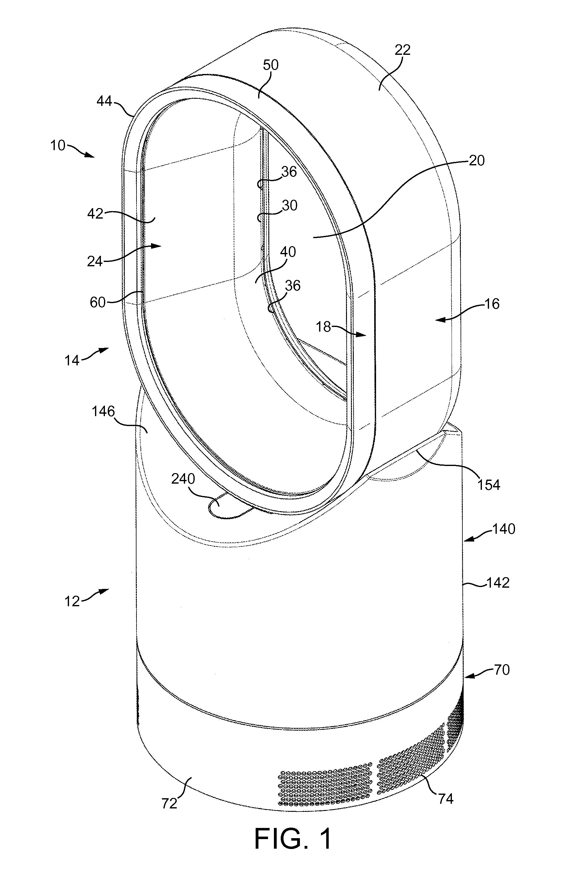
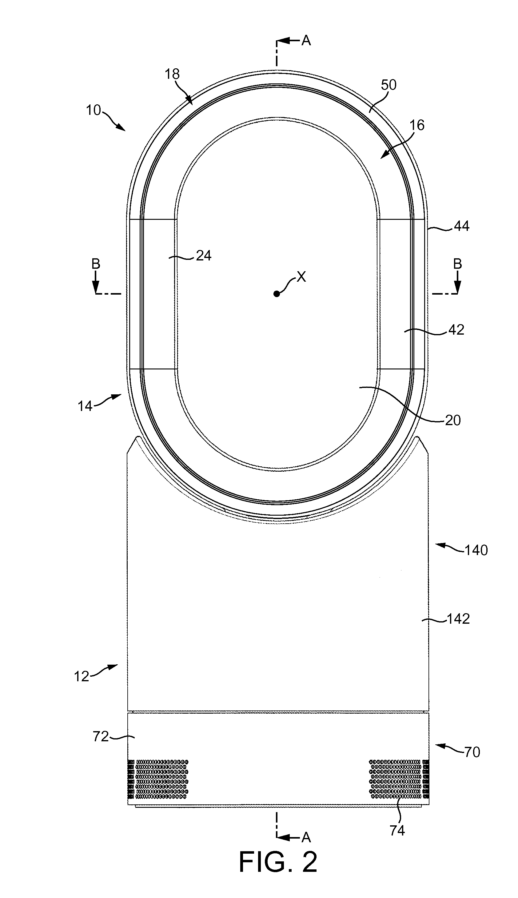
[0057]FIGS. 1 to 4 are external views of a fan assembly. In this example, the fan assembly is in the form of a humidifying apparatus 10. In overview, the humidifying apparatus 10 comprises a body 12 comprising an air inlet through which air enters the humidifying apparatus 10, and a nozzle 14 in the form of an annular casing mounted on the body 12, and which comprises a plurality of air outlets for emitting air from the humidifying apparatus 10.

[0058]The nozzle 14 is arranged to emit two different air flows. The nozzle 14 comprises a rear section 16 and a front section 18 connected to the rear section 16. Each section 16, 18 is annular in shape, and extends about a bore 20 of the nozzle 14. The bore 20 extends centrally through the nozzle 14 so that the centre of each section 16, 18 is located on the axis X of the bore 20.

[0059]In this example, each section 16, 18 has a “racetrack” shape, in that each section 16, 18 comprises two, generally straight sections located on opposite side...


PUM

PropertyMeasurementUnit
widthaaaaaaaaaa
widthaaaaaaaaaa
angleaaaaaaaaaa

Abstract

Humidifying apparatus includes a chamber, and a water tank for supplying water to the chamber. A baffle located within the chamber divides the chamber into an inlet section and an outlet section, and guides water received from the water tank along the inlet section to the outlet section. An air flow is conveyed over water stored in the outlet section of the chamber and is emitted from the apparatus. Water within both the inlet section and the outlet section of the chamber is irradiated with ultraviolet radiation. The water within the outlet section is atomized by a transducer to humidify the air flow.

Description

REFERENCE TO RELATED APPLICATIONS[0001]This application claims the priority of United Kingdom Application No. 1301573.0, filed Jan. 29, 2013, the entire contents of which are incorporated herein by reference.FIELD OF THE INVENTION[0002]The present invention relates to a fan assembly. In a preferred embodiment, the present invention provides a humidifying apparatus for generating a flow of moist air and a flow of air for dispersing the moist air within a domestic environment, such as a room, office or the like.BACKGROUND OF THE INVENTION[0003]Domestic humidifying apparatus is generally in the form of a portable appliance having a casing comprising a water tank for storing a volume of water, and a fan for creating a flow of air through an air duct of the casing. The stored water is conveyed, usually under gravity, to an atomizing device for producing water droplets from the received water. This device may be in the form of a heater or a high frequency vibrating device, such as a trans...

Claims


Application Information

Patent Timeline
Patent Type & Authority Applications(United States)
IPC IPC(8): F24F6/14
CPCF24F6/14F24F13/26F24F6/12F04D25/08F04F5/16F04F5/46Y02B30/54F24F1/01F24F6/00A61L2/10Y02B30/70F24F8/22
Inventor STANIFORTH, MARK JOSEPHBEAVIS, DANIEL JAMESPULLEN, JUDE PAULRIGGS, PAUL RICHARD
Owner DYSON TECH LTD
Why Eureka
Try Eureka