Method of prioritizing and synchronizing effect functions in an illumination device

Active Publication Date: 2014-09-11
MARTIN PROFESSIONAL
View PDF2 Cites 35 Cited by
  • Summary
  • Abstract
  • Description
  • Claims
  • Application Information

AI Technical Summary

Problems solved by technology

The light fixtures typically create the lighting effect at a distance from the light fixture itself and the light fixture is thus not as interesting and esthetic to look at.
However this is very difficult as the housing of the fixtures typical dependents on physical requirements defined by the technical specifications of the fixture such as optics, mechanics, electronics, cooling etc.
It is rather complicated to program a light show as it requires information of performance and settings of the different light fixtures in the light system.
Now that most LED fixtures have visible LEDs, some customers dislike the look of multiple light dots.
It has turned that it can be quite complicated to create nice and good looking visual effects when two different effect functions is combined, as the combination of effect functions does not always look nice.
However this requires that the central controller and the light programmer know how the different types of fixtures can combine different effect and complicates the progr

Method used


Image

  • Method of prioritizing and synchronizing effect functions in an illumination device
  • Method of prioritizing and synchronizing effect functions in an illumination device
  • Method of prioritizing and synchronizing effect functions in an illumination device

Examples


Embodiment Construction

[0008]The object of the present invention is to solve the above described limitations related to prior art. This is achieved by an illumination device and method as described in the independent claims. The dependent claims describe possible embodiments of the present invention. The advantages and benefits of the present invention are described in the detailed description of the invention.

DESCRIPTION OF THE DRAWING

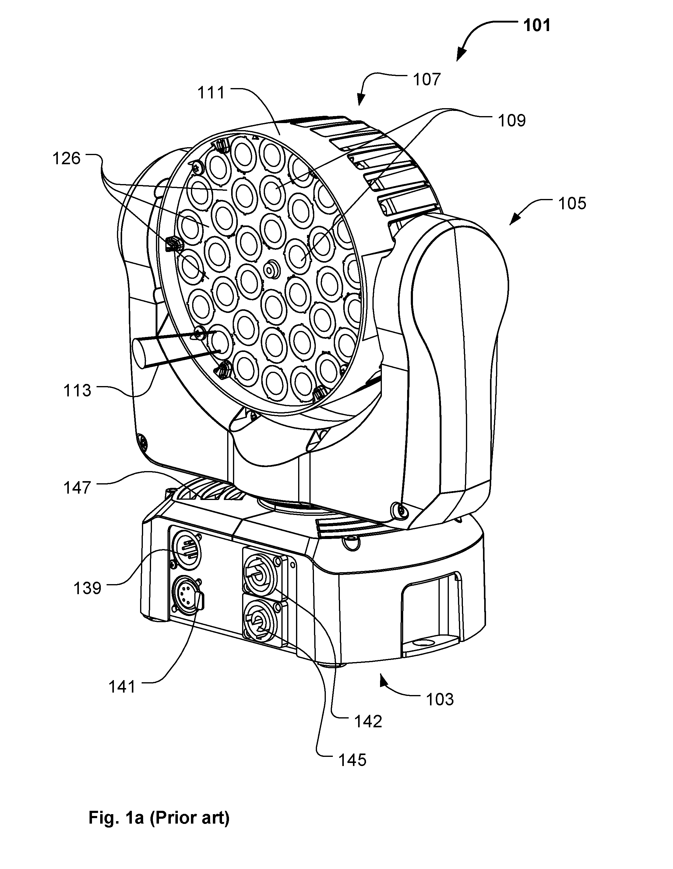
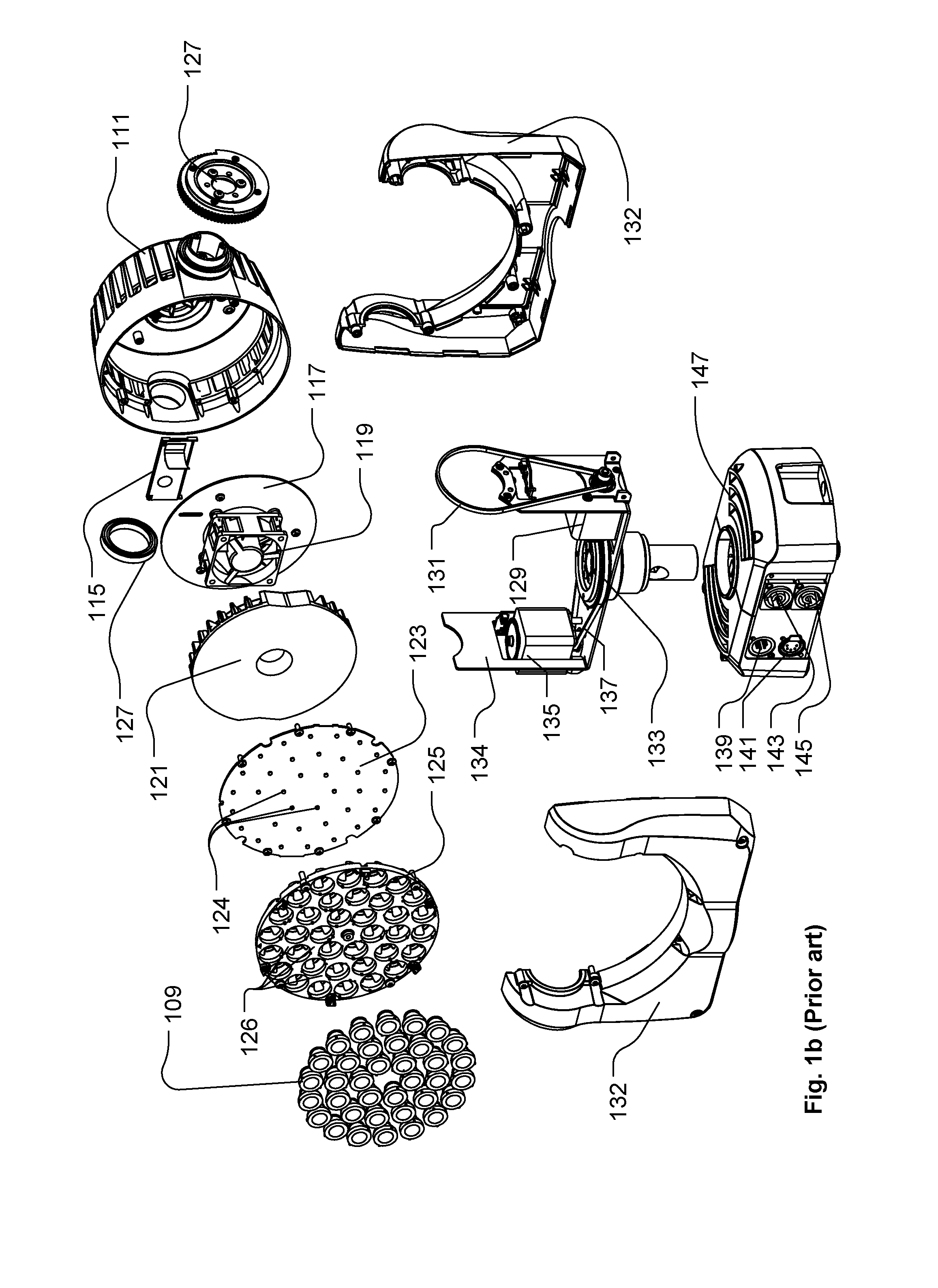
[0009]FIG. 1a-1c illustrate an example of a moving head lighting fixture according to prior art;

[0010]FIG. 2a-2c illustrate an embodiment of an illumination device according to the present invention;

[0011]FIG. 3a-3b illustrate the illumination device of FIG. 1a-1b modified into an illumination device according to the present invention;

[0012]FIG. 4a-4c illustrate another embodiment of an illumination device according the present invention;

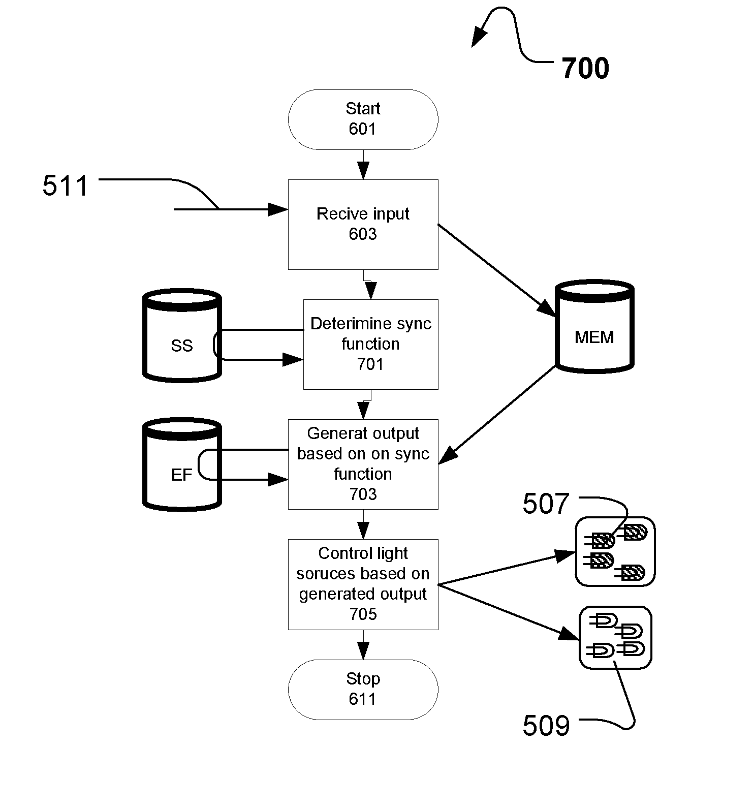
[0013]FIG. 5 illustrates a block diagram of a illumination device according to the present invention;

[0014]FIG. 6 illustrates a flow diagr...


PUM


Abstract

The present invention relates to an illumination device comprising a number of light sources arranged in a first group and in a second and controlling means adapted to control the first group and said second group individually. The controlling means is further adapted to control of light sources based on an input signal indicative of at least a first effect function and a second effect function. The first effect function generates a first output related to the light sources and said second effect function generates a second output light sources. The first and second effect functions are stored in a memory in the in the illumination device. The that controlling means is adapted to control the first and the second group of light sources based on a priority schema and/or synchronizing schema both stored in a memory in the illumination device. The priority schema comprising a number of priority rules defining how the first effect function and the second effect must be executed in relation to each other, and the synchronizing schema comprises a number of synchronizing functions defining how the controlling means must execute the first effect function and the second effect function in relation to time and in relation to each other. The present invention relates also to a method of controlling such illumination device.

Description

FIELD OF THE INVENTION[0001]The present invention relates to an illumination device comprising a number of light sources and a number of light collecting means arranged in a housing. The number of light collecting means collect light from at least one of the light sources and convert the collected into a number of source light beams and the light source beams are emitted from said housing.BACKGROUND OF THE INVENTION[0002]Light fixtures creating various effects are getting more and more used in the entertainment industry in order to create various light effects and mood lighting in connection with live shows, TV shows, sport events or as a part on architectural installation.[0003]Entertainment light fixtures creates typically a light beam having a beam width and a divergence and can for instance be wash / flood fixtures creating a relatively wide light beam with a uniform light distribution or it can be profile fixtures adapted to project an image onto a target surface. There is a tend...

Claims


Application Information

Patent Timeline
IPC IPC(8): H05B33/08H05B37/02H05B44/00
CPCH05B33/0845H05B37/0281H05B33/0857F21V21/30F21W2131/406F21V29/67F21Y2105/10F21Y2115/10F21Y2113/17H05B45/20H05B47/18H05B47/16F21Y2113/00
Inventor HINRICHS, MATTHIAS
Owner MARTIN PROFESSIONAL
Why Eureka
Try Eureka