Multi-Element antenna Calibration Technique

a multi-element, antenna technology, applied in the field of communication systems, can solve the problems of adding complexity and cos

Active Publication Date: 2014-12-04
COMMSCOPE TECH LLC
View PDF4 Cites 10 Cited by
  • Summary
  • Abstract
  • Description
  • Claims
  • Application Information

AI Technical Summary

Problems solved by technology

This method has the disadvantage of requiring additional couplers, power dividers, cables, and interconnects with preferably time-invariant responses to transport the signal to the calibration transceiver, all of which add complexity and cost.

Method used


Image

  • Multi-Element antenna Calibration Technique
  • Multi-Element antenna Calibration Technique
  • Multi-Element antenna Calibration Technique

Examples


Embodiment Construction

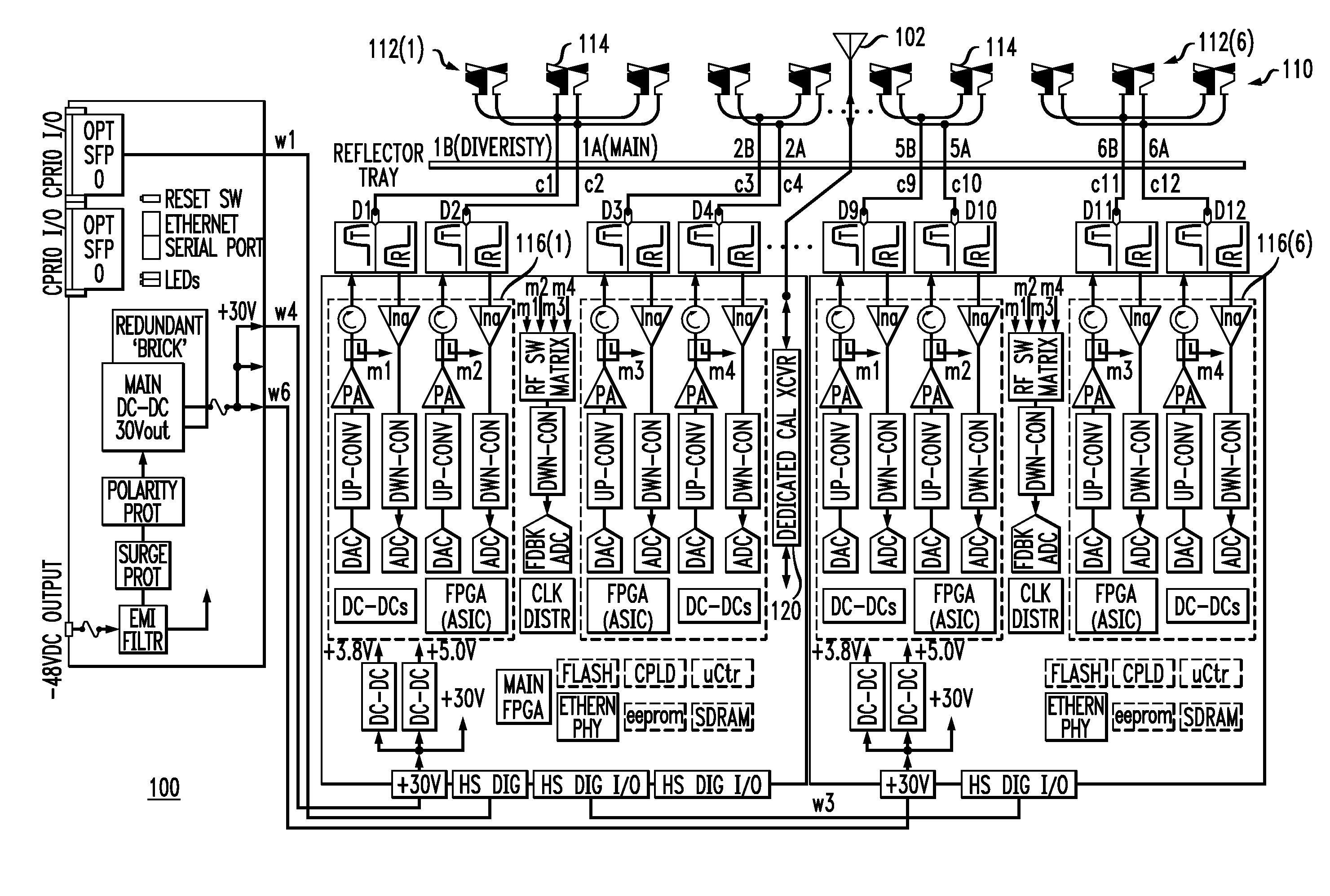
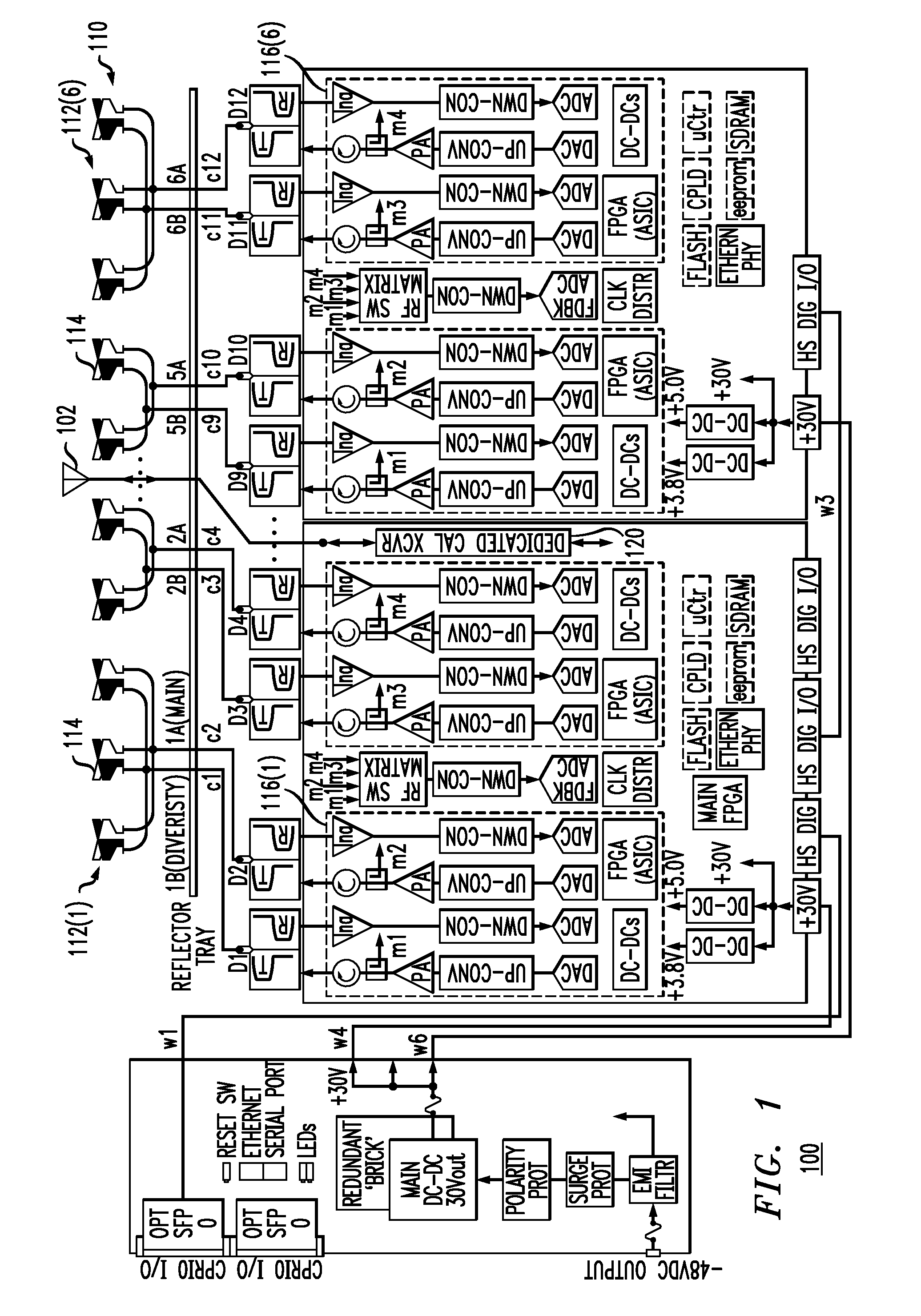
[0013]FIG. 1 is a schematic block diagram of an antenna system 100 that employs an improved calibration technique, in which an additional calibration antenna element 102 is provided to the aperture, where the technique relies on the time-invariant nature of the mutual coupling established between the radiation patterns of the other antenna elements and the calibration element.

[0014]In this particular exemplary embodiment, antenna system 100 has a dual-polarized antenna array 110 consisting of six sub-arrays 112(1)-112(6), each of which has either two or three antenna elements 114. Note that sub-arrays 112(3)-112(4) and the corresponding electronics associated with those sub-arrays are not explicitly shown in FIG. 1, but are part of exemplary antenna system 100. As shown in FIG. 1, each sub-array 112(i) has a dual-transceiver radio 116(i) that is capable of concurrently (i) providing one or two different downlink signals for radiation from one or more of the corresponding antenna ele...


PUM


Abstract

Antenna system having an antenna array with multiple sub-arrays, each having one or more antenna elements, is calibrated using a distributed calibration antenna element, such as a leaky coaxial cable, that spans across at least two and possibly all of the sub-arrays. To calibrate the transmit (TX) paths of the sub-arrays, TX calibration test signals are transmitted by the sub-arrays, captured by the distributed calibration element, and processed by a corresponding calibration radio. To calibrate the receive (RX) paths of the sub-arrays, an RX calibration test signal is generated by the calibration radio, transmitted by the distributed calibration element, captured by the sub-arrays, and processed by their corresponding radios. Cross-correlation between the calibration and captured signals is performed to derive the complex gain of each sub-array transmitter and receiver, which provides information for aligning the gain, phase, and delay of the different TX and RX paths of the antenna array.

Description

CROSS-REFERENCE TO RELATED APPLICATIONS[0001]This application claims the benefit of the filing date of U.S. provisional application No. 61 / 590,099, filed on Jan. 24, 20012 as attorney docket no. 1052.101PROV, the teachings of which are incorporated herein by reference in their entirety.BACKGROUND[0002]1. Field of the Invention[0003]The present invention relates to communication systems and, more specifically but not exclusively, to antenna arrays, such as those for cellular communication systems.[0004]2. Description of the Related Art[0005]This section introduces aspects that may help facilitate a better understanding of the invention. Accordingly, the statements of this section are to be read in this light and are not to be understood as admissions about what is prior art or what is not prior art.[0006]An active antenna comprises an array of radiating elements or sub-arrays of radiating elements that are excited in a particular set of relative amplitude and phase excitations to cre...

Claims


Application Information

Patent Timeline
Patent Type & Authority Applications(United States)
IPC IPC(8): H01Q3/26
CPCH01Q3/26H01Q1/246H01Q3/267H01Q13/203H01Q21/08
Inventor MACA, GREGORY A.VEIHL, JONATHON C.
Owner COMMSCOPE TECH LLC
Why Eureka
Try Eureka