Exhaust emission control device for rough terrain crane

a technology of emission control device and crane, which is applied in the direction of machines/engines, transportation and packaging, separation processes, etc., can solve the problems of reducing design flexibility, reducing design flexibility, and reducing design flexibility, so as to achieve excellent visibility and favorable visual field

Active Publication Date: 2015-01-01
TADANO LTD
View PDF9 Cites 13 Cited by
  • Summary
  • Abstract
  • Description
  • Claims
  • Application Information

AI Technical Summary

Benefits of technology

[0025](9) As described above, the diesel oxidation catalyst, the selective catalytic reduction, and the decomposition reactor tube, which are laid out in a compact manner, are disposed on the left end or the right end of the rear end portion of the vehicle, and therefore, during crane ope

Problems solved by technology

However, the constituent elements of the exhaust emission control device vary depending on the intended use, and the size of vehicle and the mounting space in the vehicle is naturally restricted.
Moreover, interference between the exhaust emission control device and the driver seat should

Method used


Image

  • Exhaust emission control device for rough terrain crane
  • Exhaust emission control device for rough terrain crane
  • Exhaust emission control device for rough terrain crane

Examples


Embodiment Construction

[0031]Hereinafter, a preferred embodiment of the invention is described in detail with reference to the drawings as appropriate.

Overall Configuration and Features

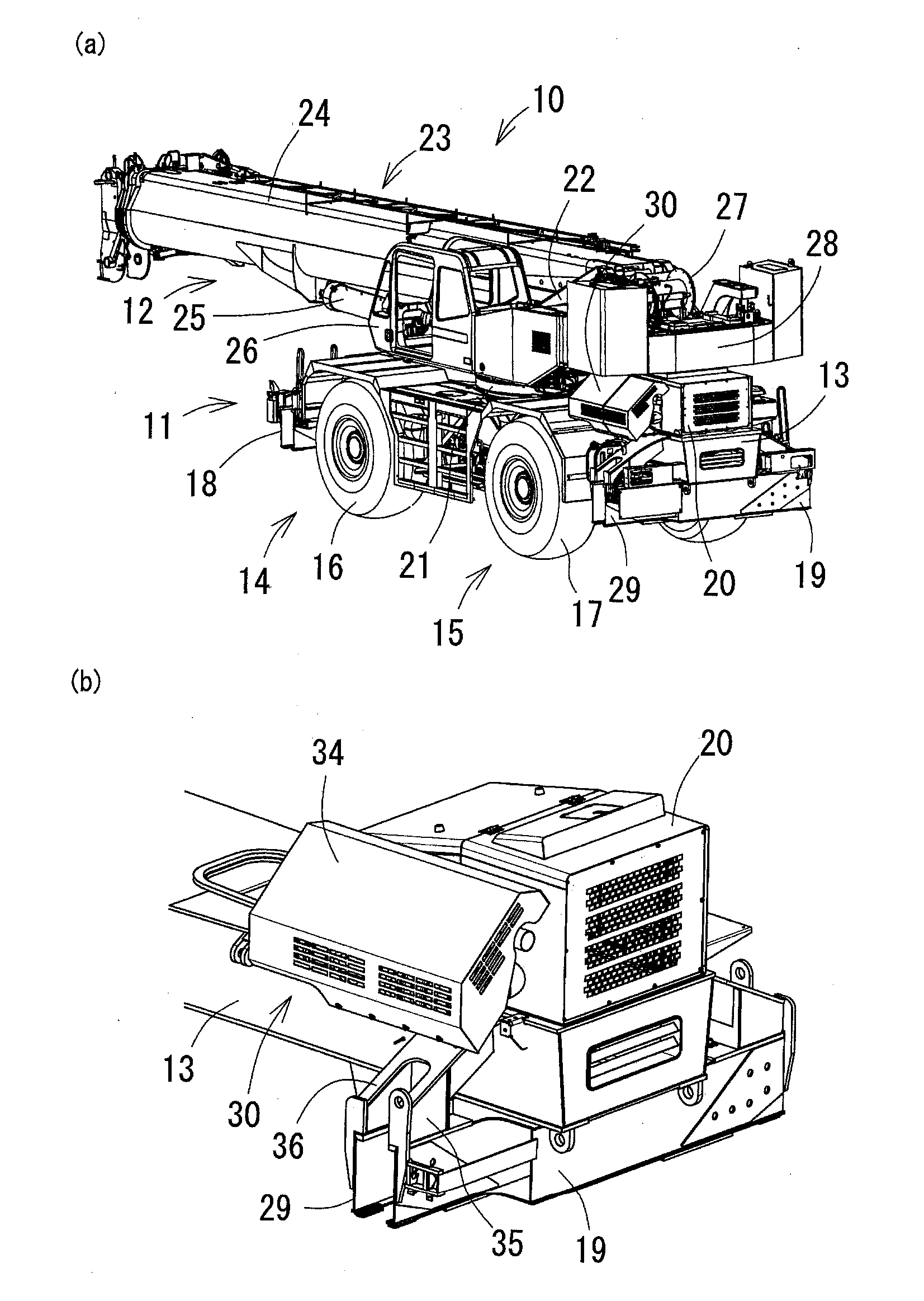
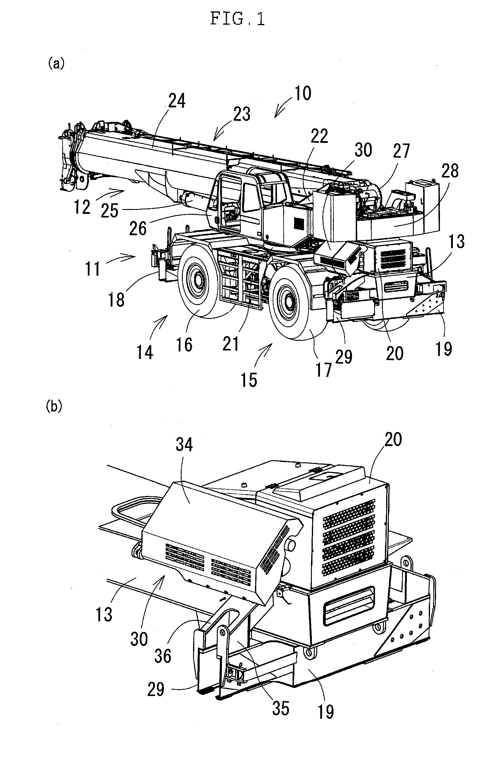
[0032]FIGS. 1(a) and 1(b) are perspective views of a rough terrain crane 10 according to one embodiment of the invention, in which FIG. 1(a) is a perspective view of the appearance and FIG. 1(b) is an enlarged perspective view of the essential portion.

[0033]The rough terrain crane 10 has a carrier 11 and a working unit 12.

[0034]The carrier 11 has a lower frame 13 and the lower frame 13 is provided with a front axle 14 and a rear axle 15. A diesel engine serving as the drive source of the front axle 14 and the rear axle 15 is mounted on a rear end portion of the lower frame 13. Wheels 16 and 17 of the front axle 14 and the rear axle 15, respectively, are driven through a transmission that is not illustrated and are steered by a hydraulic cylinder that is not illustrated. A front outrigger 18 and a rear outrigger 19 are provi...


PUM


Abstract

A new rough terrain crane has an exhaust emission control device that has a DOC, a DRT, and a SCR. The DOC and the DRT are connected in series and disposed along a longitudinal direction of a vehicle. A rear end of the DOC is positioned at the front side relative to a rear end of an engine. The SCR is disposed in parallel to the DOC and both devices are disposed above a support member of a rear outrigger. The SCR is disposed on the upper side relative to the DOC at a position close to the engine.

Description

CROSS-REFERENCE TO RELATED APPLICATION[0001]This application claims priority on Patent Application No. 2013-135846 filed in Japan on Jun. 28, 2013.FIELD OF THE INVENTION[0002]The present invention relates to the structure of an exhaust emission control device for diesel engines to be mounted in rough terrain crane vehicles.DESCRIPTION OF THE RELATED ART[0003]The exhaust emission of diesel engines contain particulate matter (hereinafter referred to as “PM”), nitride oxide (hereinafter referred to as “NOx”), and the like. In order to prevent air pollution, a device which prevents these substances from being emitted to the air has been developed heretofore. Such a device is referred to as an exhaust emission control device (or an after-treatment device).[0004]The exhaust emission control device contains a diesel particulate filter for collecting the PM (hereinafter referred to as “DPF”), a diesel oxidation catalyst (hereinafter referred to as “DOC”) for removing the NOx, a decompositio...

Claims


Application Information

Patent Timeline
IPC IPC(8): F01N3/035B66C13/52B01D53/94
CPCB66C13/52B01D53/94F01N3/035F01N3/2066F01N3/106F01N13/011Y02T10/24F01N2590/08F01N13/009F01N2340/04Y02A50/20Y02T10/12
Inventor TERATA, KIMIHIKOSEKO, SHINYAHONDA, RYO
Owner TADANO LTD
Why Eureka
Try Eureka