Ink jet printing apparatus and ink jet printing method

a printing apparatus and ink jet technology, applied in printing, other printing apparatus, etc., can solve problems such as inappropriate image printing, and achieve the effect of relaxing the negative pressure in the print head and stably ejecting

Active Publication Date: 2015-03-26
COPYER
View PDF4 Cites 5 Cited by
  • Summary
  • Abstract
  • Description
  • Claims
  • Application Information

AI Technical Summary

Benefits of technology

[0015]According to the present invention, the opening and closing unit opens the communication path in accordance with the pressure in the print head to bring the outside and the print head into communication with each other, thus relaxing the negative pressure in the print head. This enables the ink in the closed ink tank and in the print head to be stably ejected.

Problems solved by technology

This may preclude the ink from being appropriately ejected, leading to inappropriate image printing.

Method used


Image

  • Ink jet printing apparatus and ink jet printing method
  • Ink jet printing apparatus and ink jet printing method
  • Ink jet printing apparatus and ink jet printing method

Examples


first embodiment

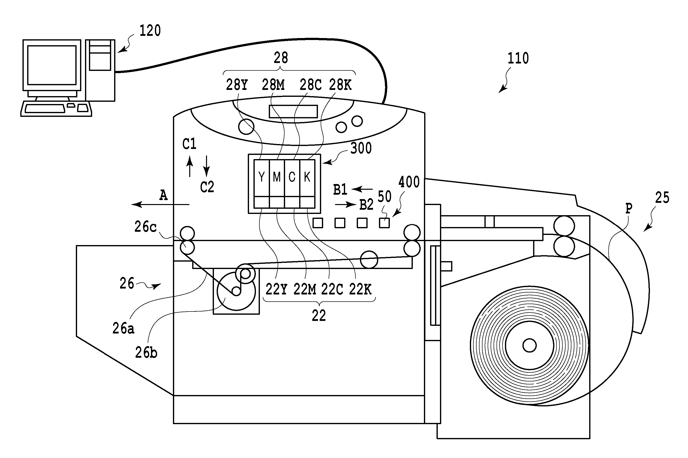
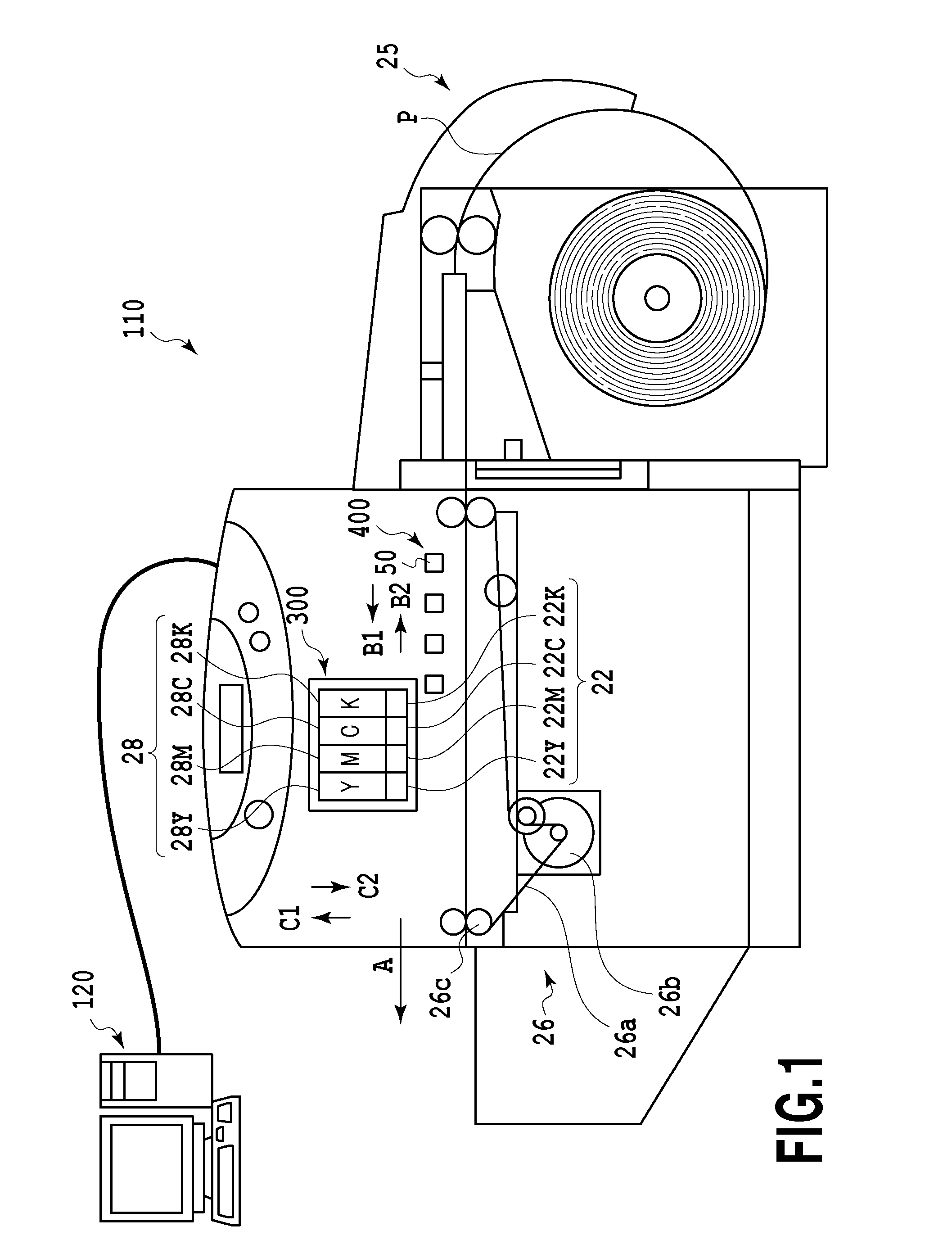
[0031]FIG. 1 is a diagram of a conceptual example of a configuration of a full line ink jet printing apparatus (hereinafter also referred to as a “printer”) 110.

[0032]The printer 110 is connected to a host apparatus 120 configured as a personal computer or the like to transmit image information to the printer 110. The printer 110 includes four print heads 22 (22K, 22C, 22M, and 22Y) capable of ejecting ink and which are arranged in juxtaposition in a direction in which rolled paper P serving as a print medium is conveyed (the direction of arrow A). The print heads 22K, 22C, 22M, and 22Y are print heads configured to eject black, cyan, magenta, and yellow, respectively. Each of the print heads 22 includes a plurality of nozzles with a plurality of ejection ports through which the corresponding ink is ejected using an ejection energy generating element such as an electrothermal transducing element (heater) or a piezo element. When the electrothermal transducing element is used, the el...

second embodiment

[0062]As shown in FIG. 8, a plurality of print heads may all be connected to a single buffer chamber. The remaining part of the configuration of a second embodiment is similar to the corresponding part of the first embodiment and will thus not be described. In the present example, four print heads 22 (22Y, 22M, 22C, and 22K) are connected to a single buffer chamber 16 via first valves 17 (17Y, 17M, 17C, and 17K). When the negative pressure in the print head 22Y is equal to or higher a predetermined negative pressure, the CPU 100 enables the negative pressure in the print head 22Y to be relaxed by preliminarily reducing the pressure in the buffer chamber 16 and then temporarily opening the first valve 17Y. This also applies to the other print heads 22M, 22C, and 22K.

[0063]In the above first embodiment, the valves 17 and 20 and the pump 18 are controlled based on a result of comparison of the predetermined negative pressure VA with the negative pressure (V+V1) resulting from accumulat...

third embodiment

[0066]A printing apparatus according to a third embodiment enables the inside of the print head 22 to be pressed through the communication path 15 in the print head 22 in view of a case where the filter 27 provided in the communication path 15 is wet with the ink.

[0067]The filter 27 is provided in the communication path 15 to prevent foreign matter such as dust from entering the print head 22 through the communication path 15. If the foreign matter enters the print head 22 and migrates into the nozzle, the ink may be inappropriately ejected. Like the filter 13, the filter 27 has an average width of approximately 10 μm, is formed of SUS, and includes metal fibers woven in the filter 13.

[0068]If the ink in the print head 22 comes into contact with the filter 27 or the ink flows through the filter 27 to make the filter 27 temporarily wet with the ink, a membrane of the ink is formed in the meshes of the filter 27 to hinder gas from passing through the filter 27. Such a membrane is firm...


PUM


Abstract

An ink jet printing apparatus includes a print head configured to be able to eject an ink fed from an ink tank that contains the ink in a closed space so as to apply a negative pressure to the ink, a communication path configured to allow a liquid chamber in the print head to communicate with an outside of the liquid chamber, an opening and closing unit configured to open and close the communication path, and a control unit configured to open the communication path in accordance with a pressure in the print head via the opening and closing unit, to bring the liquid chamber and the outside into communication with each other.

Description

BACKGROUND OF THE INVENTION[0001]1. Field of the Invention[0002]The present invention relates to an ink jet printing apparatus and an ink jet printing method in which an image is printed using an ink tank that contains ink in a closed space so as to apply a negative pressure to the ink and a print head that can eject the ink fed from the ink tank.[0003]2. Description of the Related Art[0004]In an ink jet printing apparatus, ink with a negative pressure applied thereto is fed from an ink tank to a print head and then ejected through ejection ports in the print head using an ejection energy generating element such as an electrothermal transducing element (heater) or a piezo element. Such a printing apparatus is used in a narrow space, for example, on a checkout counter or in a shelf in a store or on a desk in an office. Thus, there has been a demand for a reduction in the size of the printing apparatus.[0005]For a reduced size of the printing apparatus, ideally the print head and the ...

Claims


Application Information

Patent Timeline
Patent Type & Authority Applications(United States)
IPC IPC(8): B41J2/175B41J2/14
CPCB41J2/14B41J2/17566B41J2/175B41J2/1752B41J2/17556B41J29/38B41J2002/17579
Inventor YAMAGUCHI, KENROSUGAI, TAKASHIOTA, NORITAKA
Owner COPYER
Why Eureka
Try Eureka