Ink jet printing apparatus and ink jet printing method
a printing apparatus and ink jet technology, applied in printing, other printing apparatus, etc., can solve problems such as inappropriate image printing, and achieve the effect of relaxing the negative pressure in the print head and stably ejecting
- Summary
- Abstract
- Description
- Claims
- Application Information
AI Technical Summary
Benefits of technology
Problems solved by technology
Method used
Image
Examples
first embodiment
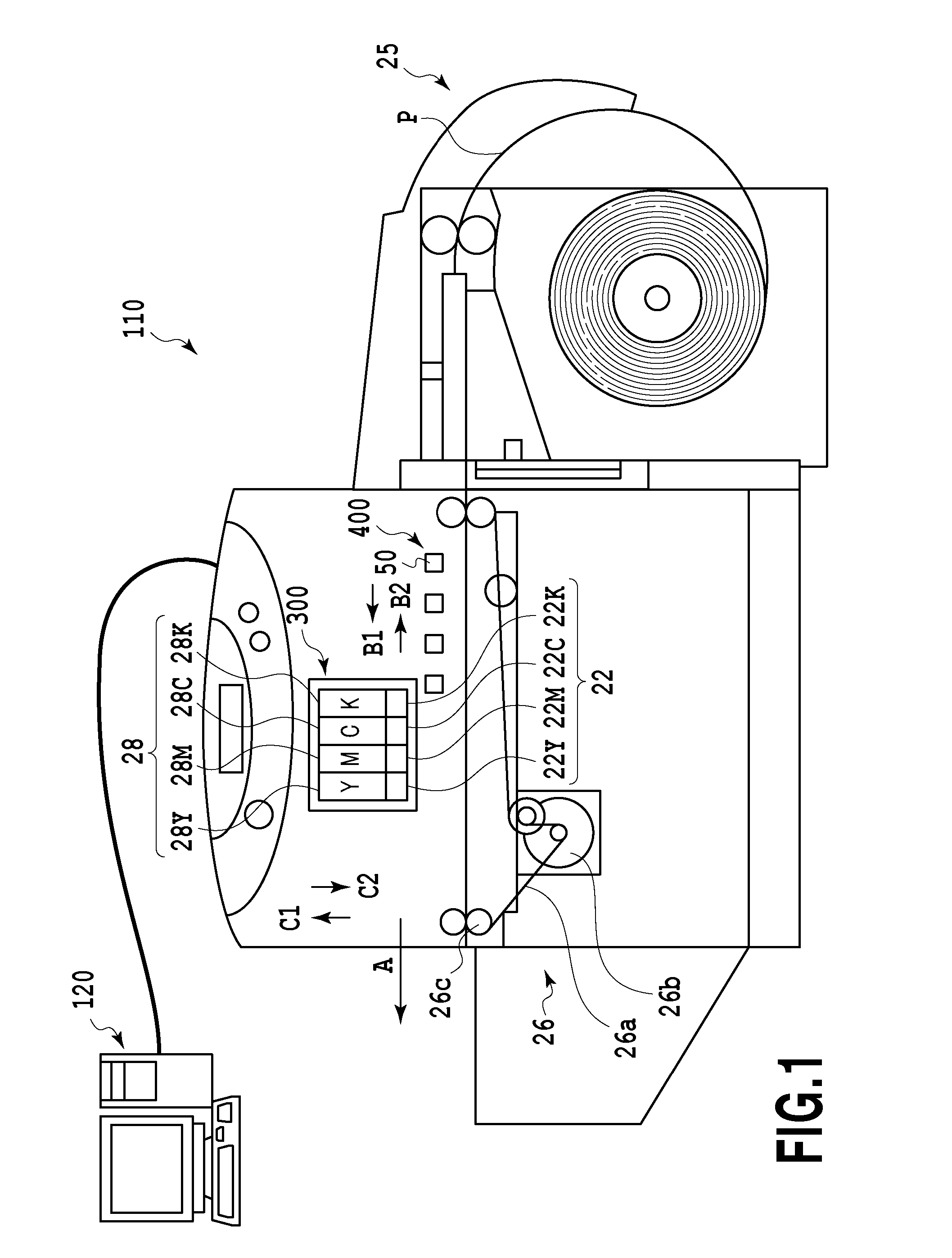
[0031]FIG. 1 is a diagram of a conceptual example of a configuration of a full line ink jet printing apparatus (hereinafter also referred to as a “printer”) 110.
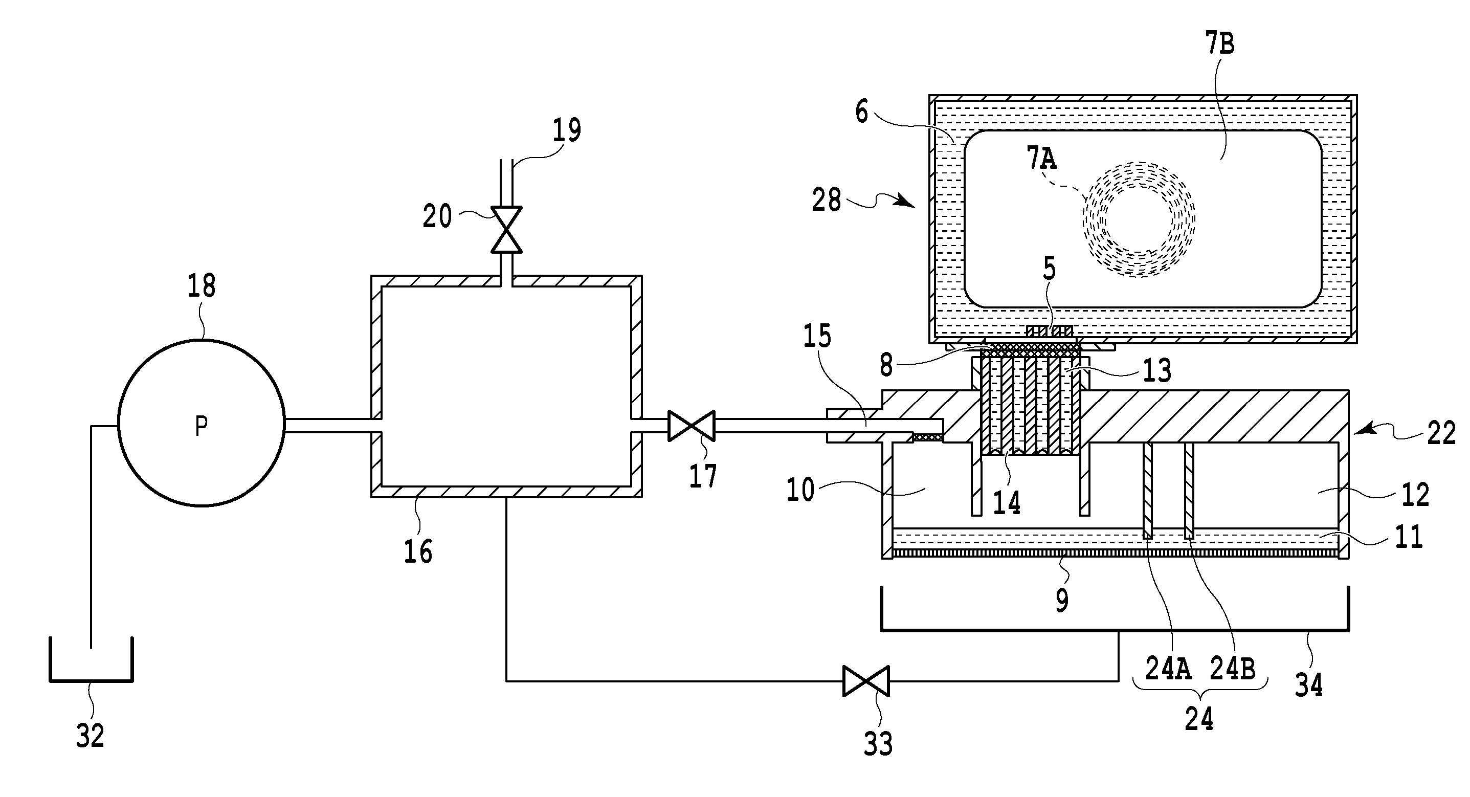
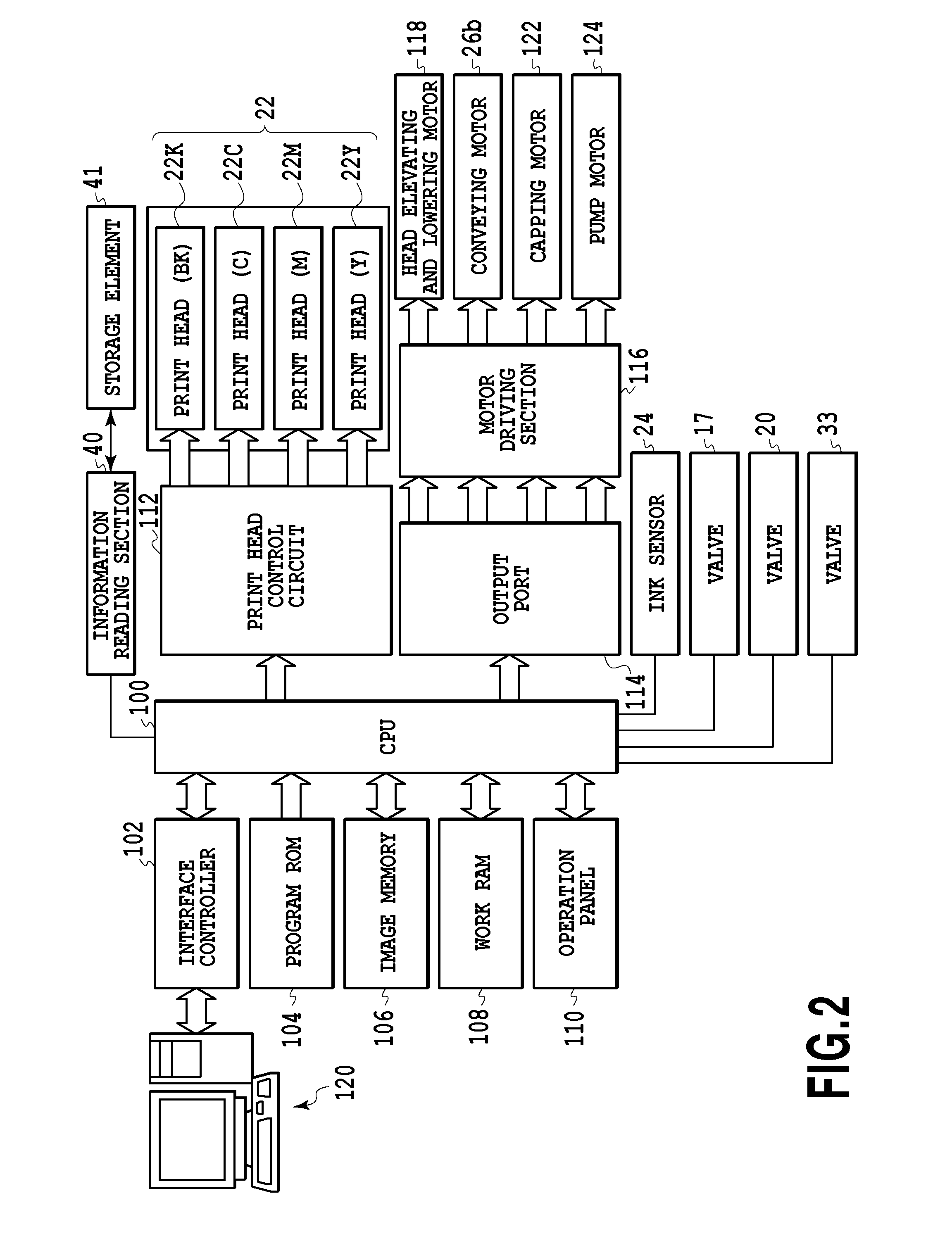
[0032]The printer 110 is connected to a host apparatus 120 configured as a personal computer or the like to transmit image information to the printer 110. The printer 110 includes four print heads 22 (22K, 22C, 22M, and 22Y) capable of ejecting ink and which are arranged in juxtaposition in a direction in which rolled paper P serving as a print medium is conveyed (the direction of arrow A). The print heads 22K, 22C, 22M, and 22Y are print heads configured to eject black, cyan, magenta, and yellow, respectively. Each of the print heads 22 includes a plurality of nozzles with a plurality of ejection ports through which the corresponding ink is ejected using an ejection energy generating element such as an electrothermal transducing element (heater) or a piezo element. When the electrothermal transducing element is used, the el...
second embodiment
[0062]As shown in FIG. 8, a plurality of print heads may all be connected to a single buffer chamber. The remaining part of the configuration of a second embodiment is similar to the corresponding part of the first embodiment and will thus not be described. In the present example, four print heads 22 (22Y, 22M, 22C, and 22K) are connected to a single buffer chamber 16 via first valves 17 (17Y, 17M, 17C, and 17K). When the negative pressure in the print head 22Y is equal to or higher a predetermined negative pressure, the CPU 100 enables the negative pressure in the print head 22Y to be relaxed by preliminarily reducing the pressure in the buffer chamber 16 and then temporarily opening the first valve 17Y. This also applies to the other print heads 22M, 22C, and 22K.
[0063]In the above first embodiment, the valves 17 and 20 and the pump 18 are controlled based on a result of comparison of the predetermined negative pressure VA with the negative pressure (V+V1) resulting from accumulat...
third embodiment
[0066]A printing apparatus according to a third embodiment enables the inside of the print head 22 to be pressed through the communication path 15 in the print head 22 in view of a case where the filter 27 provided in the communication path 15 is wet with the ink.
[0067]The filter 27 is provided in the communication path 15 to prevent foreign matter such as dust from entering the print head 22 through the communication path 15. If the foreign matter enters the print head 22 and migrates into the nozzle, the ink may be inappropriately ejected. Like the filter 13, the filter 27 has an average width of approximately 10 μm, is formed of SUS, and includes metal fibers woven in the filter 13.
[0068]If the ink in the print head 22 comes into contact with the filter 27 or the ink flows through the filter 27 to make the filter 27 temporarily wet with the ink, a membrane of the ink is formed in the meshes of the filter 27 to hinder gas from passing through the filter 27. Such a membrane is firm...
PUM
 Abstract
Description
Claims
Application Information
 - R&D
- Intellectual Property
- Life Sciences
- Materials
- Tech Scout
- Unparalleled Data Quality
- Higher Quality Content
- 60% Fewer Hallucinations
Browse by: Latest US Patents, China's latest patents, Technical Efficacy Thesaurus, Application Domain, Technology Topic, Popular Technical Reports.
© 2025 PatSnap. All rights reserved.Legal|Privacy policy|Modern Slavery Act Transparency Statement|Sitemap|About US| Contact US: help@patsnap.com


