Wireless power communication

Active Publication Date: 2015-04-23
PHILIPS IP VENTURES BV
View PDF3 Cites 42 Cited by
  • Summary
  • Abstract
  • Description
  • Claims
  • Application Information

AI Technical Summary

Benefits of technology

[0014]The duration of the ramping can vary. For example, the time period for ramping during a bit time may depend on the number of transitions within the bit time. In addition, the time period for ramping to the first duty cycle may differ from the time period for ramping to the second duty cycle

Problems solved by technology

There are a variety of factors that complicate development of efficient systems.
This inverse relationship between the distance and the mutual inductance may impose restrictions on the operating parameters of the system.
This system may gain some efficiency due to the utilization of additional coils in order to maint

Method used


Image

  • Wireless power communication
  • Wireless power communication
  • Wireless power communication

Examples


Example

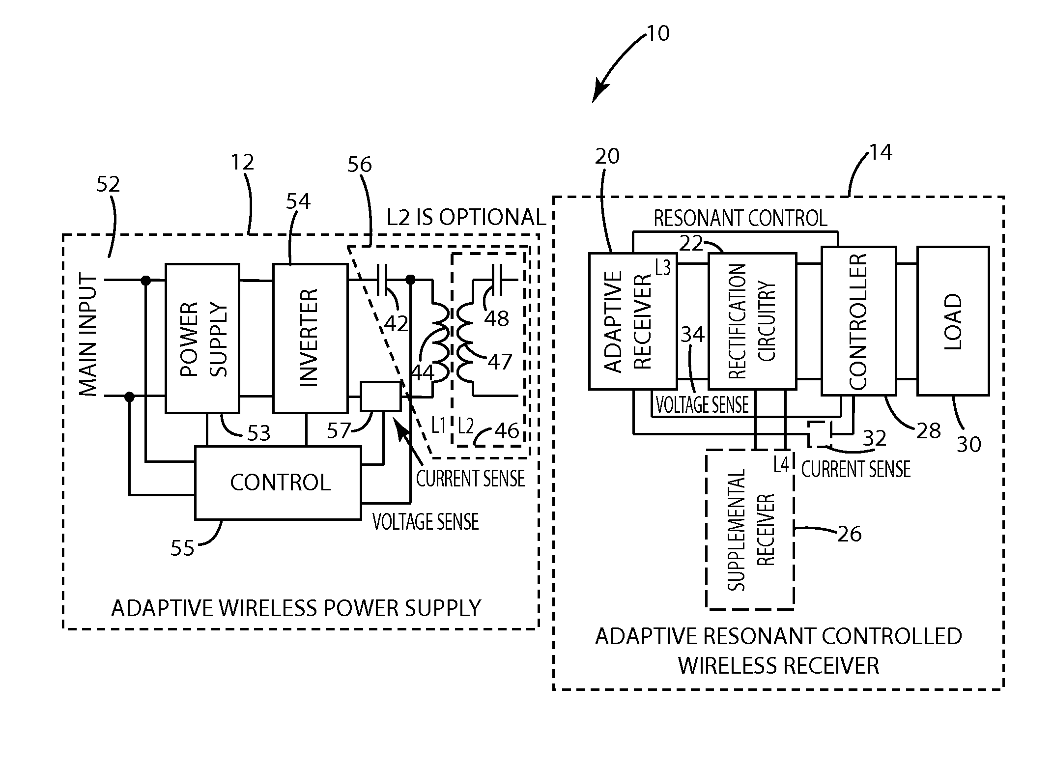
[0042]A wireless power supply system in accordance with an embodiment of the present invention is shown in FIG. 1 and designated 10. A remote device in accordance with one embodiment of the present invention can enable flexible power transfer, for example to allow the remote device to control the amount of power it receives, which can be used to communicate and / or provide an appropriate amount of power to the load. The wireless power supply system 10 includes a remote device 14 configured to receive wireless power and a wireless power supply 12 configured to transmit power. Although described in connection with a single remote device 14, the present invention is not limited to power transfer to just one remote device 14 and is well suited for supplying power to multiple remote devices, such as by supplying power sequentially or simultaneously. One or more of the remote devices 14 in this circumstance may be conventional remote devices.

[0043]The remote device can control the amount o...


PUM


Abstract

A remote device in accordance with the present invention includes an adaptive power receiver that receives wireless power from the wireless power supply by induction. The adaptive power receiver may be switched among two or more modes of operation, including, for example, a high-Q mode and a low-Q mode. By controlling the duty cycle of the switching between modes, the amount of energy received by the adaptive receiver may be controlled to communicate to the wireless power supply. This control is a form of adaptive resonance communication or Q control communication. Distortion can be reduced or eliminated by ramping between duty cycles with adjustment to intermediate duty cycle values.

Description

BACKGROUND OF THE INVENTION[0001]The present invention relates to wireless power transfer.[0002]Wireless power supply systems allow power to be transferred to an electronic device, such as a portable device, without the need for direct electrical connections. Wireless power transfer may be achieved using inductors, which produce magnetic fields when current flows through them. Conversely, current may be induced in an inductor when in the presence of a magnetic field, such as the magnetic field produced by another inductor. If two inductors are placed in proximity and one inductor is driven with a current, then the other inductor will produce a current even though the two inductors are not directly connected. This interrelationship between the two inductors is generally called inductive coupling, and many have used this phenomenon to transfer power without electrical connections.[0003]In fact, many of the fundamental principles of wireless power transfer have been known for 100 years...

Claims


Application Information

Patent Timeline
IPC IPC(8): H02J5/00H01F38/14
CPCH01F38/14H02J5/005H04B5/0037H04L25/4902H02J50/12H02J50/80H04L25/0266H02J50/50H02J50/60H03H7/38
Inventor TAYLOR, JOSHUA B.MOORE, COLIN J.GRUICH, ROBERT D.
Owner PHILIPS IP VENTURES BV
Why Eureka
Try Eureka