Tractor with Hybrid Power System

a hybrid power system and tractor technology, applied in the field of agricultural tractors, can solve the problems of inability to downsize the engine, the hybrid technology approach cannot be directly applied to the application of the tractor, etc., and achieve the effects of reducing the stress on the associated electric motor, improving the control of the torque applied, and improving the control of the traction during operation

Active Publication Date: 2015-07-30
AGCO SA (FR)
View PDF17 Cites 27 Cited by
  • Summary
  • Abstract
  • Description
  • Claims
  • Application Information

AI Technical Summary

Benefits of technology

[0009]The electrical connection between the electric motor and the electric generator facilitates an infinitely variable transmission of power between the internal combustion engine and the wheels or tracks thereby dispensing of the requirement for a traditional mechanical transmission. Of course is should be appreciated that at least one gear box may be required between the electrical motor and the wheels or tracks to deliver the necessary torque. However the requirement for multiple input-to-output ratios is no longer present.
[0011]In existing tractors the diesel engines employed typically have their maximum power at around 2000 rpm whilst their maximum torque is delivered at around 1500 rpm with about a 15% rise in torque between the point of maximum power and the point of maximum torque. When used during high load applications (such as cultivation) the engine is driven around the maximum power point (2000 rpm) and any overload in power demand is catered for by a rise in torque through a drop in engine speed, thus avoiding stalling of the engine. The inventor has recognised that in order to exploit the most efficient output of an engine, it must be driven around the point of maximum torque. In order to deliver an equivalent maximum power to existing tractors the engine used for a diesel electric system in a tractor should be upsized. This allows the engine to be driven at its most efficient engine speed while still delivering the required power.
[0017]The at least one electrical motor that is arranged to deliver a propulsion force to the wheels or tracks can form part of a second motor / generator which is connected to the battery. In addition to serving as an electrical motor, the second motor / generator can alternatively operate as a generator which converts torque recovered from the wheels or tracks into electrical energy which can be delivered to, and stored by, the battery. The recovery of torque from the wheels or tracks can provide a braking effect thus, advantageously, reducing overall power consumption.
[0023]In an alternative embodiment the tractor comprises a pair of front wheels and a pair of rear wheels wherein each wheel has associated therewith a respective electric motor arranged to deliver a propulsion force to the wheel via a respective mechanical drive connection, each electrical motor being electrically connected to, and powered by, the electrical generator. The provision of separate electric motors for each wheel dispenses with the need for differential gearboxes whilst still delivering four-wheel drive. Furthermore, the dedicated electric motors allows for better control of the torque applied to each wheel thus improving the control of traction during operation.
[0024]The mechanical drive connections associated with the two rear wheels may be connected by a clutch which provides a disengageable mechanical connection between the drive connections of the two rear wheels. Advantageously, this delivers a mechanical lock between the two rear wheels which reduces stress on the associated electric motors and simulates a conventional differential lock.
[0026]In yet another embodiment an auxiliary electrical motor is provided and is drivingly connected, via an auxiliary clutch, to the mechanical drive connection between the engine and the PTO shaft. When the auxiliary clutch is open the PTO shaft is driven by the auxiliary electrical motor which is electrically connected to, and powered by, the electrical generator. Therefore, the PTO shaft can be disconnected from the engine and driven solely by the auxiliary motor. Advantageously, this arrangement lends itself well to low power PTO applications when variable speed output is beneficial. Furthermore, the auxiliary motor can be used upon starting of the PTO shaft before closing the auxiliary clutch. This delivers a smooth increase in the PTO speed and reduces stress in the mechanical drive connection to the engine.

Problems solved by technology

This hybrid technology approach cannot be mapped directly across to tractor application because the maximum power output of the engine is demanded for long periods of time.
Therefore, downsizing of the engine is not practical.

Method used


Image

  • Tractor with Hybrid Power System
  • Tractor with Hybrid Power System
  • Tractor with Hybrid Power System

Examples


first embodiment

[0063]FIG. 6 shows an alternative modification to which the same or similar parts will not be described any further. The tractor 300 comprises a disengageable mechanical drive connection between the two rear propulsion motor / generators 121,122. The disengageable drive connection comprises a shaft 327 and a clutch 328. This additional drive connection can be selectively engaged by the driver by appropriate control of clutch 328 to provide a mechanical lock between the propulsion drives of the two rear wheels 101,102. This simulates a rear differential lock present on existing tractors and serves to deliver power from both associated motors during periods of unbalanced traction.

[0064]A further adaption of the first embodiment is shown in FIG. 7 in the form of fourth embodiment. In this case the front propulsion motor / generators 123,124 are replaced by a single front propulsion motor / generator 429, the torque generated by which is distributed to the front wheels 103,104 via a front dif...

sixth embodiment

[0066]The tractor 600 in accordance with the invention shown in FIG. 9 utilizes a single front propulsion motor / generator 429 (as described above in relation to FIG. 7) in combination with a rear propulsion motor / generator 533 (as described above in relation to FIG. 8). Advantageously, the arrangement shown in FIG. 9 requires only two motor / generator modules for propulsion of the tractor 600 whilst still delivering four wheel drive.

[0067]In a further modified arrangement tractor 700 shown in FIG. 10 delivers a propulsion force to all four wheels 101-104 from a single propulsion motor / generator 737, the torque generated by which is distributed to the front and rear differential gearboxes 430, 534 via a torsen, or torque sensitive differential unit 738. Alternatively, a conventional or limited slip clutch may be used. Although shown offset from the longitudinal centre line of the tractor 700, the torsen 738 and / or the propulsion motor / generator 737 may be located centrally on the trac...

eighth embodiment

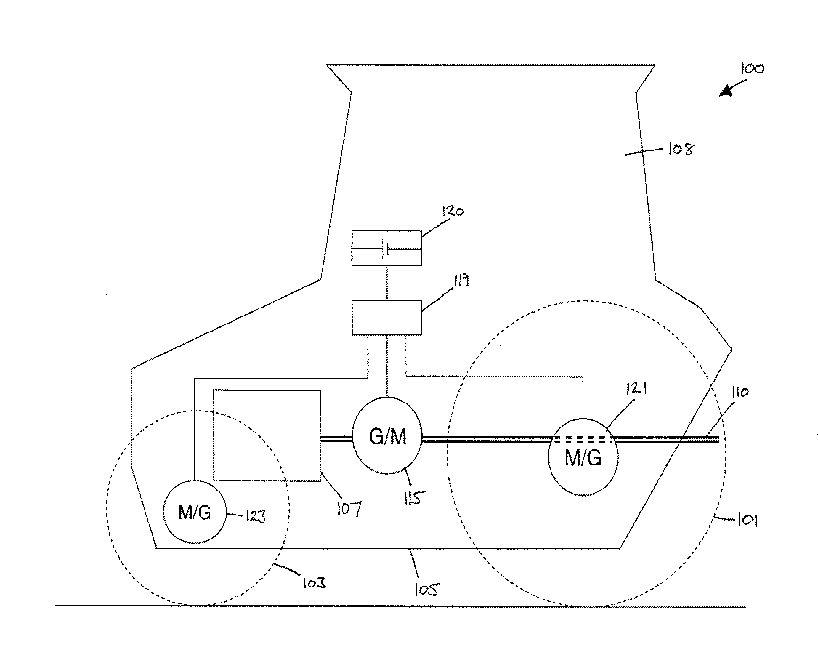
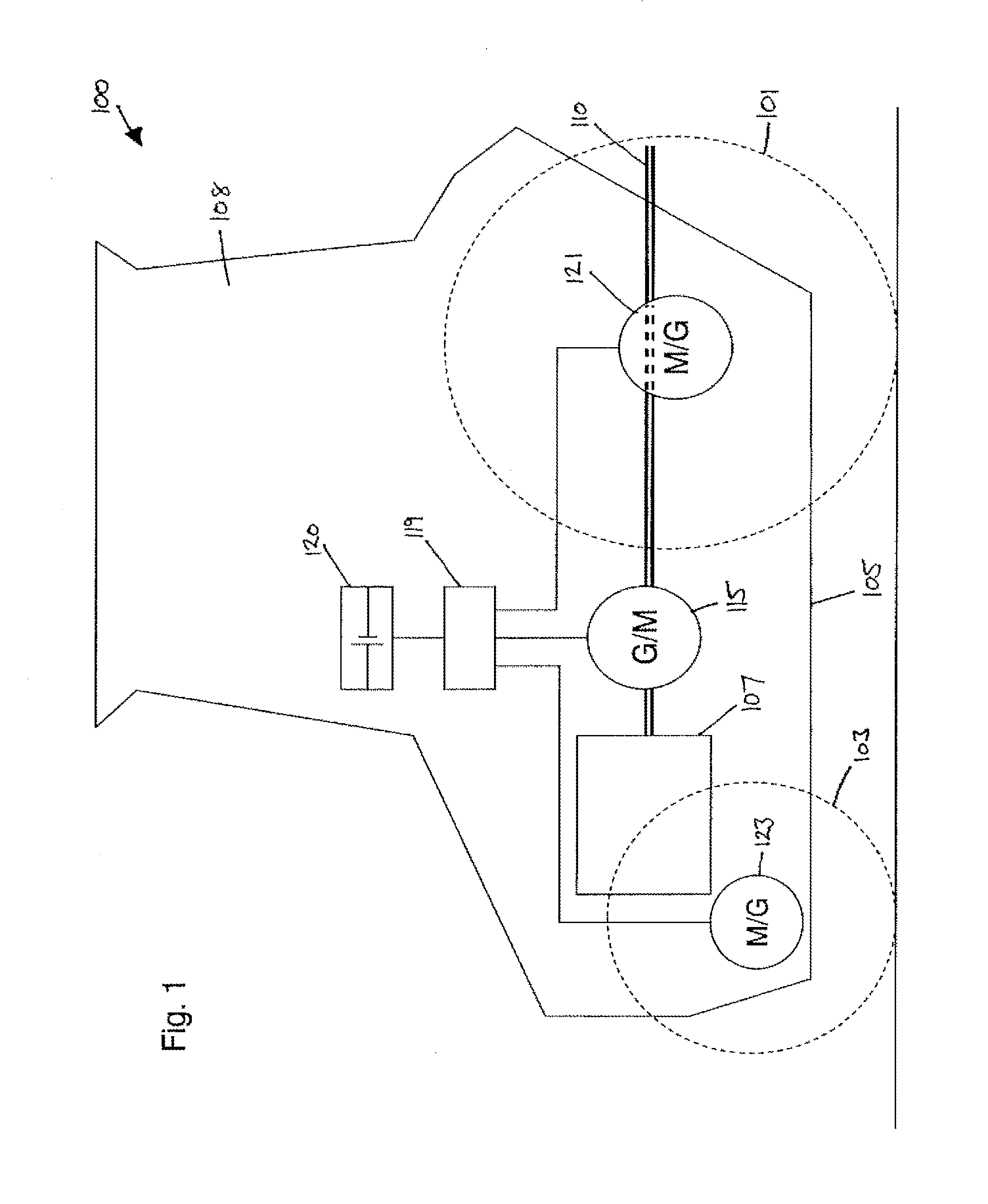
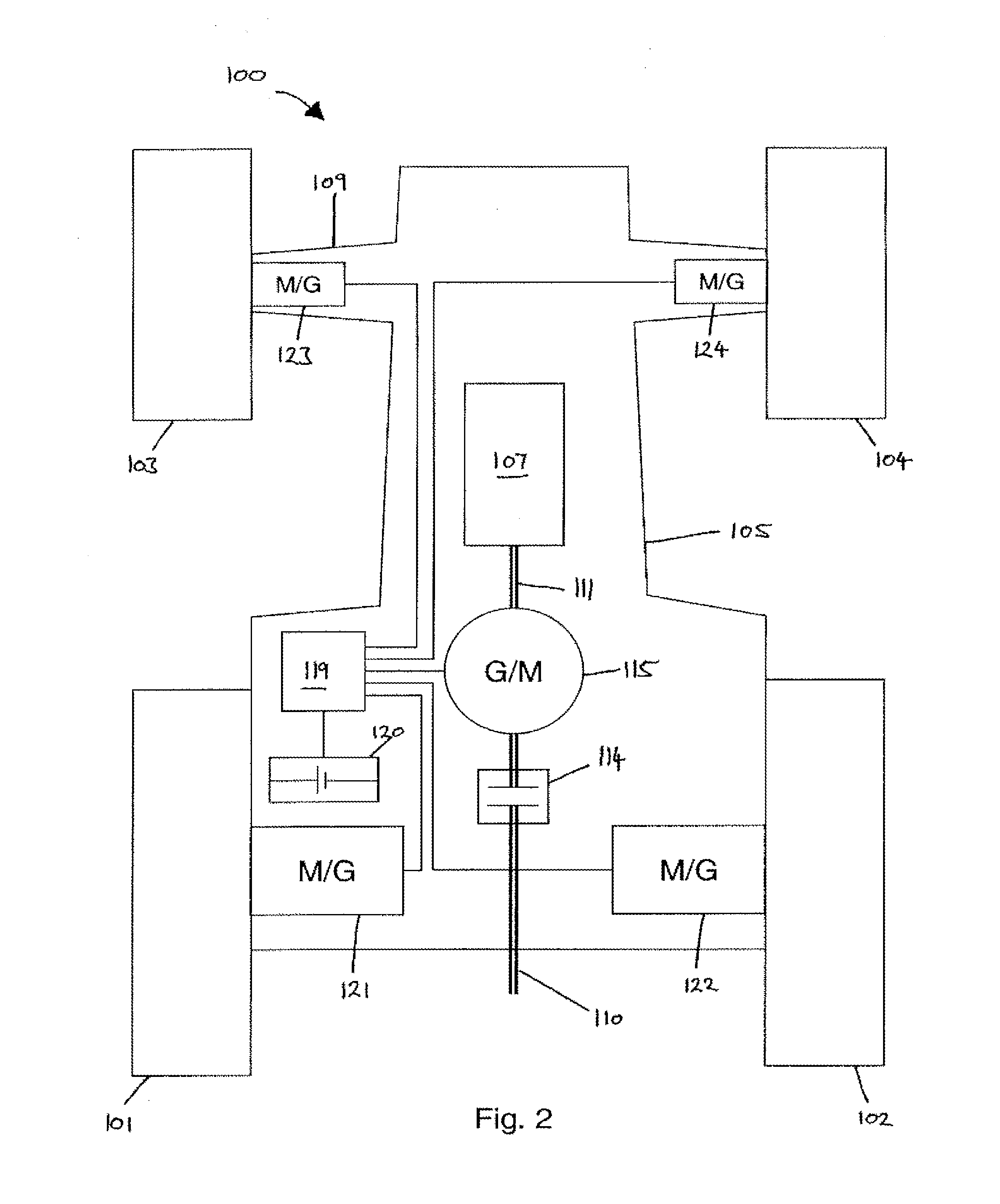
[0068]With reference to FIG. 11, the invention is shown in the form of a tractor 800. As in previously described embodiments, the tractor 800 comprises an engine 107 drivingly connected to a PTO shaft 110 via a PTO clutch 114. A first motor / generator 115 is drivingly connected to the driveshaft 111 running from the engine 117. Electrical energy generated by the first motor / generator 115 is conveyed to power control unit 119 for distribution to a single propulsion motor / generator 839 or to battery 120.

[0069]Propulsion motor / generator 839 is drivingly connected to a first input / output of an epicyclic gearbox 840. Driveshaft 111 is drivingly connected to a second input / output of the epicyclic gearbox 840 via meshed gears 841, 842, 843. The torque generated by the drive shaft 111 is summed with the torque generated by the propulsion motor / generator 839 by the epicyclic gearbox 840 and transmitted to a rear differential gearbox 534 via a drive connection 844. Therefore, the rear wheels 1...


PUM


Abstract

A tractor includes an internal combustion engine for delivering torque, wheels or tracks for imparting a propulsive force to the ground, and a power takeoff shaft for delivering torque to implements attached thereto. The power takeoff shaft is driven by a mechanical drive connection to the engine. An electrical motor / generator is drivingly connected to the engine, and at least one electrical motor is arranged to deliver a propulsion force to the wheels or tracks. The motor is electrically connected to, and powered by, the electrical motor / generator. A battery is connected to the electrical motor / generator and to the electrical motor so that electrical energy can be passed therebetween. The motor / generator can also operate as a motor so that the power takeoff shaft is at least partially powered by electrical energy from the battery.

Description

CROSS-REFERENCE TO RELATED APPLICATION[0001]This application is a continuation application of U.S. application Ser. No. 13 / 696,500, entitled TRACTOR WITH HYBRID POWER SYSTEM, filed Nov. 6, 2012, which is incorporated herein by reference.FIELD OF THE INVENTION[0002]The invention relates to agricultural tractors which employ an internal combustion engine for a primary source of power, wheels or tracks for imparting a propulsive force to the ground, and a power takeoff shaft for delivering torque to implements attached thereto.BACKGROUND[0003]Employed for agricultural purposes for decades, tractors have a basic architecture that has not changed significantly since their conception. Still today modern tractors typically include an internal combustion engine mounted forwardly of a transaxle. The transaxle itself houses a transmission and the required drive mechanics to drive a pair of rear wheels attached thereto. The engine and transaxle together commonly provide the chassis for support...

Claims


Application Information

Patent Timeline
Patent Type & Authority Applications(United States)
IPC IPC(8): B60K6/20B60K17/28
CPCB60K6/20Y10S903/903B60K2025/022B60K17/28B60K6/46B60K2025/005B60W10/08B60W20/00B60W30/1888B60Y2200/221Y02T10/62
Inventor HUSSON, GEOFFROYSHUTE, MALCOLMMENIER, GABRIEL
Owner AGCO SA (FR)
Why Eureka
Try Eureka