Connector protection structure for motor

Inactive Publication Date: 2015-07-30
TOYOTA JIDOSHA KK
View PDF4 Cites 4 Cited by
  • Summary
  • Abstract
  • Description
  • Claims
  • Application Information

AI Technical Summary

Benefits of technology

The present invention provides a connector protection structure for a motor that can be easily assembled onto the motor case, and is designed to protect the connector from damage during collisions. The protection member is securely fixed to the motor case and includes a protection section around the connector, a fixing section on the motor case, and a support section on the vehicle's side surface. A hook portion is formed to prevent the deviation of the connector in the through hole due to the input of collision load. The protection section includes a side protection section and an upper protection section, and the protection member can be fixed to the motor case while penetrating the stud through the support section and tightening it with a bolt. This improves the assembly capability of the protection member and ensures reliable protection of the connector in the event of collisions.

Problems solved by technology

In this case, it is difficult to fix the protection member such that both the first and second side walls of the protection member are seated on outer surfaces of the motor case, and there is a problem in that the assembly capability of the protection member is inferior.
More specifically, operations are required to provisionally tighten the first side wall of the fixing section with a bolt, then provisionally tighten the second side wall of the fixing section with a bolt, and finally tighten the bolts of the side walls to fix the protection member on the motor case, which results in an inferior assembly capability.
Even if the protection member is fixed in this manner, due to manufacturing error of the components or the like, there may be cases where one of the first and second side walls is not seated on the outer surfaces of the motor case, in which case, the tightening force by the bolt becomes insufficient, and there is a risk that loosening of the bolt tends to occur.

Method used


Image

  • Connector protection structure for motor
  • Connector protection structure for motor
  • Connector protection structure for motor

Examples


Embodiment Construction

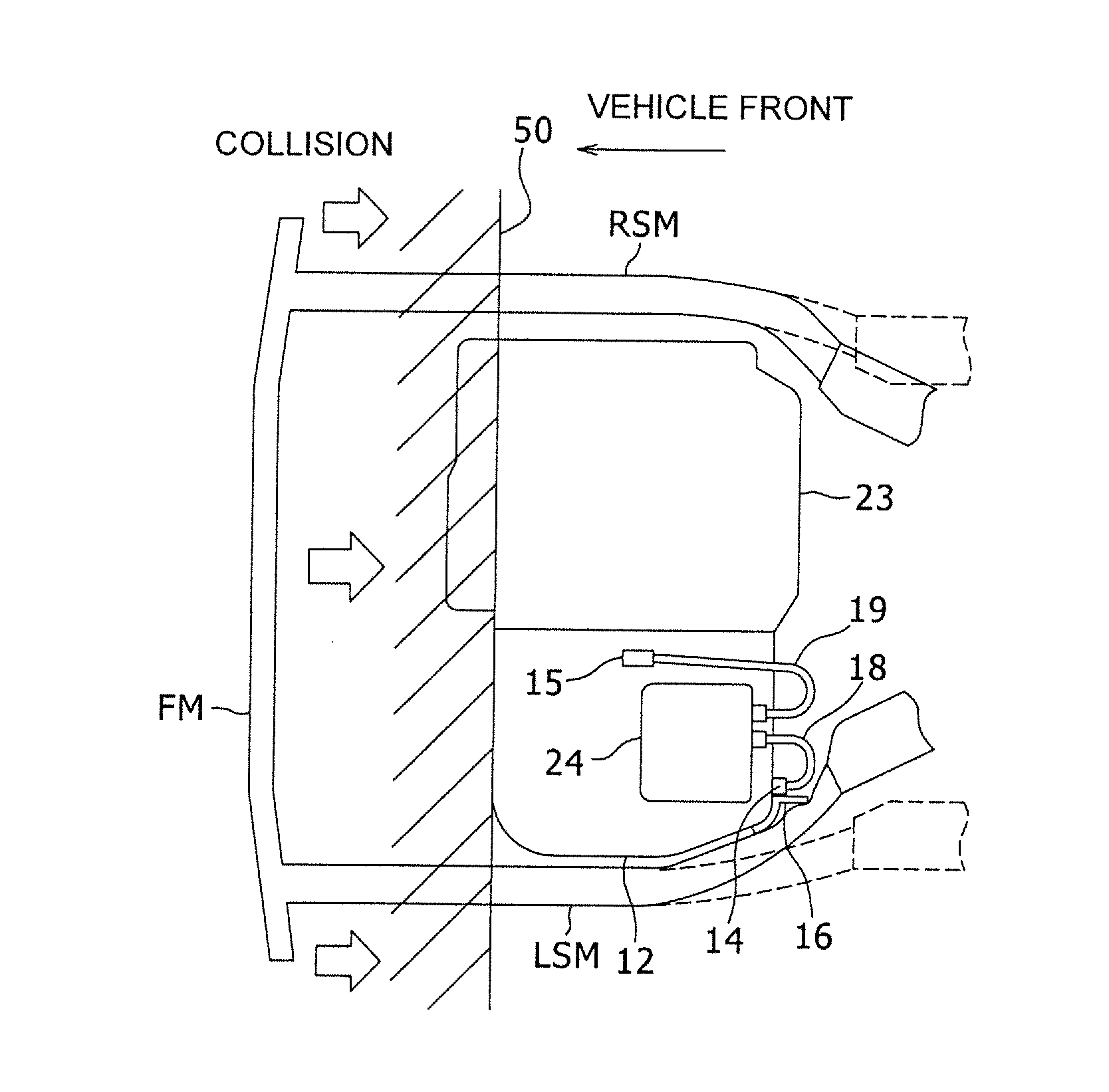
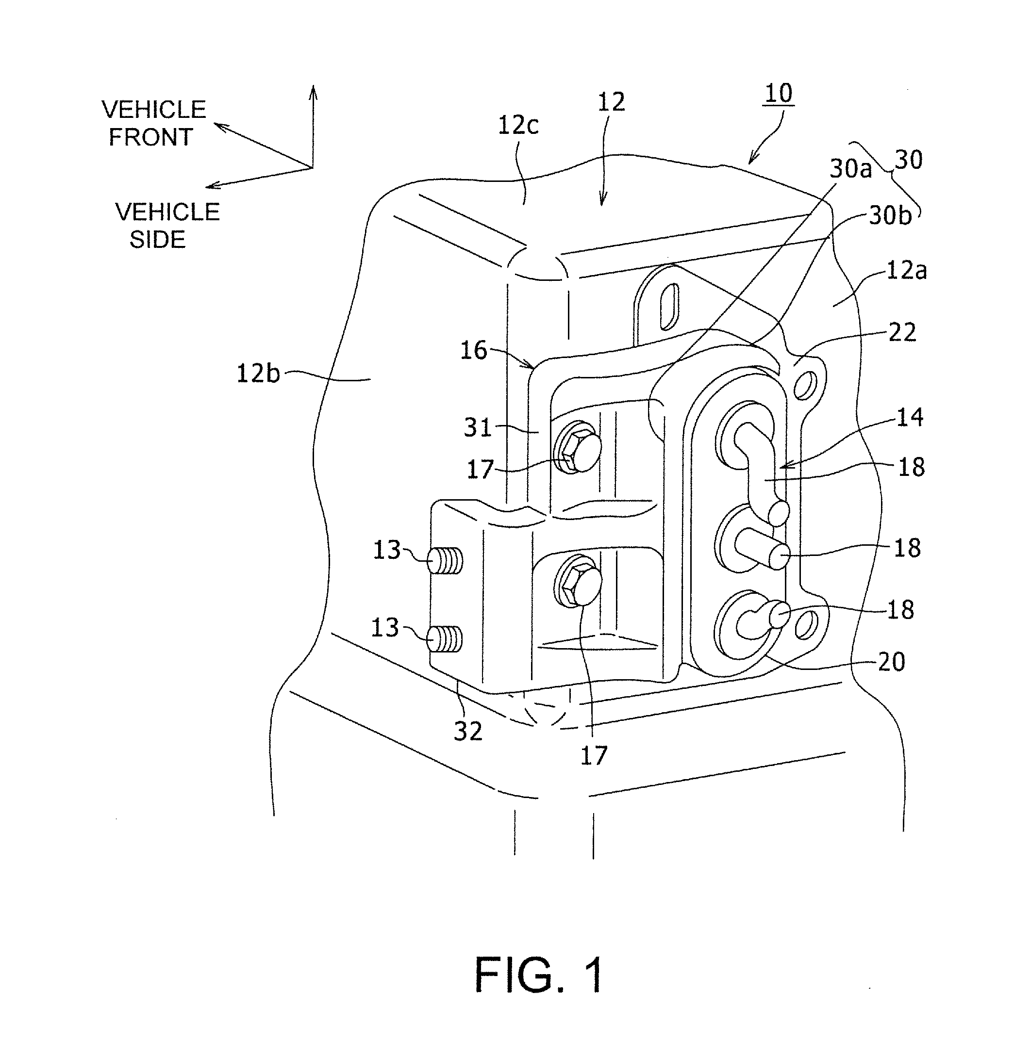
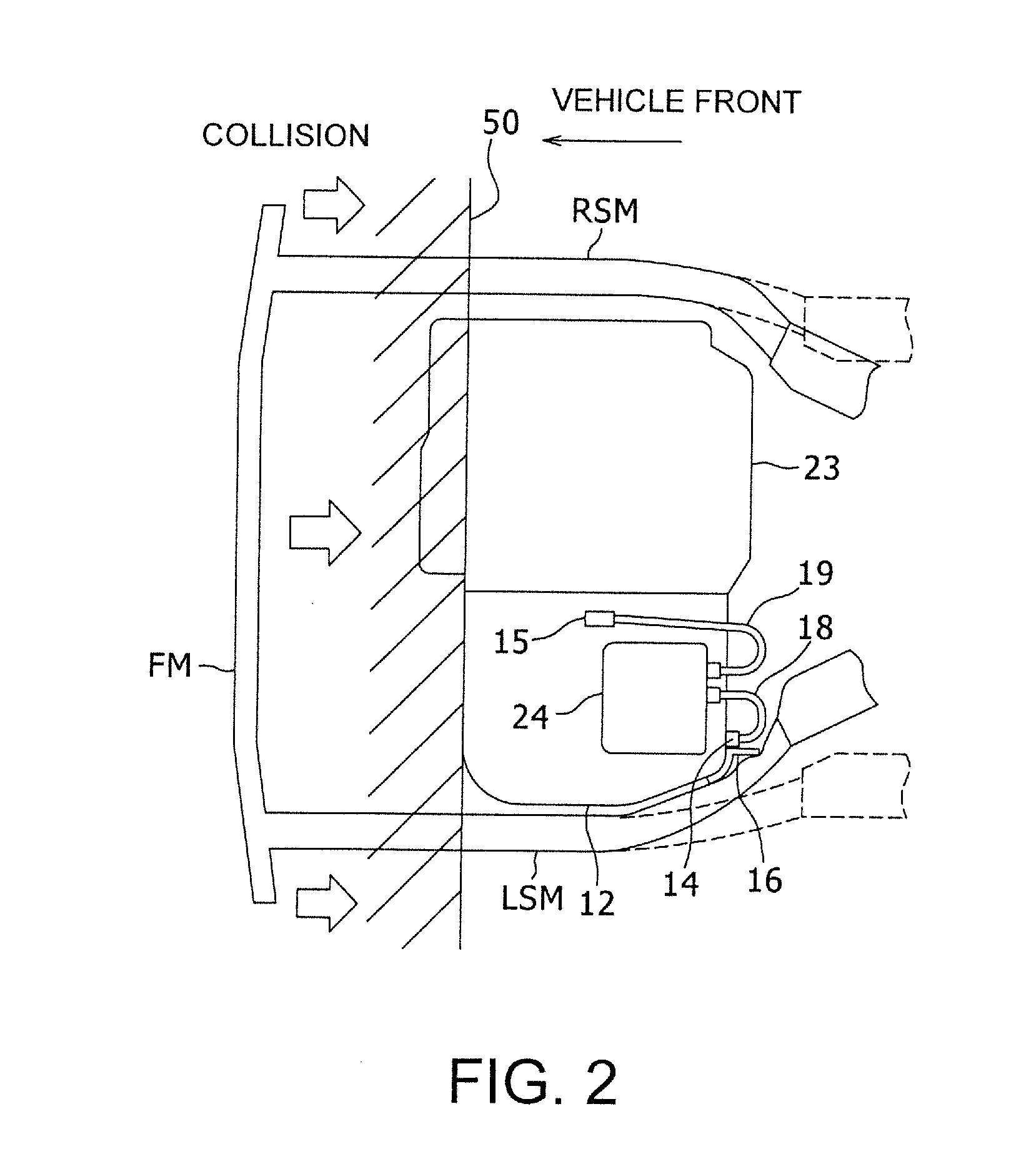
[0022]A preferred embodiment of the present invention will now be described in detail with reference to the accompanying drawings. In this description, the specific shape, material, numerical value, direction, etc. are provided merely as examples, to facilitate understanding of the present invention, and may be suitably changed according to the usage, objective, specification, etc. In addition, in the following description, when a plurality of embodiments and modified configurations are included, it is understood that the characteristics thereof may be suitably combined.

[0023]In the following description, an example configuration will be described in which the motor connector protection structure is applied to a hybrid electric vehicle equipped with a motor and an engine. However, the present invention is not limited to such a configuration, and may be applied to an electric automobile equipped only with the motor as a traveling motive power source. Moreover, a number of the motor g...


PUM


Abstract

A connector protection structure of motor includes a motor case that houses the motor, a connector that is placed on an outer surface of the motor case, and a protection member that is provided between the connector and a side member (LSM) of a vehicle, and that is fixed on the motor case. The protection member includes a protection section that is provided in a projected arrangement around the connector, a fixing section that is linked to the protection section and that is fixed by a bolt on a rear surface of the motor case, and a support section that is linked to the fixing section, that includes a through hole through which a stud, provided in a projected arrangement on a side surface of the motor case, penetrates, and that is supported on the side surface by the stud.

Description

PRIORITY INFORMATION[0001]This application claims priority to Japanese Patent Application No. 2014-013075, filed on Jan. 28, 2014, which is incorporated herein by reference in its entirety.TECHNICAL FIELD[0002]The present invention relates to a connector protection structure for a motor that protects a connector by preventing contact of a side member of a vehicle, which is deformed during collision of the vehicle, with the connector in a motor case.BACKGROUND ART[0003]There are known vehicles such as an electric automobile that drives a vehicle with a motor and a hybrid electric automobile equipped with a motor and an engine. In these vehicles, in order to improve the traveling performance, an inverter and a high-voltage power cable that control electric power of a high-voltage battery and supply the electric power to the motor are provided. Thus, various considerations are being made with respect to a collision accident. In collisions of these vehicles, in the case of non-serious c...

Claims


Application Information

Patent Timeline
IPC IPC(8): H02K5/22
CPCH02K2203/09H02K5/225
Inventor TOOYAMA, EIICHIMORIUCHI, YASUYUKIHIROTA, MICHITO
Owner TOYOTA JIDOSHA KK
Why Eureka
Try Eureka