Image processing apparatus and image processing method

a technology of image processing and image processing apparatus, applied in the field of image processing technology, can solve the problem of difficult to simply compare a plurality of moving images, and achieve the effect of facilitating diagnosis and facilitating comparison

Inactive Publication Date: 2015-09-10
KONICA MINOLTA INC
View PDF6 Cites 21 Cited by
  • Summary
  • Abstract
  • Description
  • Claims
  • Application Information

AI Technical Summary

Benefits of technology

[0013]According to the present invention, image processing technology enabling proper and effective comparison for diagnosis between a plurality of moving images in displaying moving images in which target regions of human bodies or animal bodies are photographed can be provided.
[0014]These and other objects, features, aspects and advantages of the present invention will become more apparent from the following detailed description and the accompanying drawings.

Problems solved by technology

In such cases, it is difficult to simply compare a plurality of moving images because of a phase difference caused by a difference in photographing timing, and a difference in moving speed.

Method used


Image

  • Image processing apparatus and image processing method
  • Image processing apparatus and image processing method
  • Image processing apparatus and image processing method

Examples


embodiment 1

1. Embodiment 1

[0047]A radiographic dynamic image photographing system according to Embodiment 1 of the present invention is described below.

[0048]

[0049]The radiographic dynamic image photographing system according to Embodiment 1 photographs a radiographic dynamic image of a target region of a subject that is a human body or an animal body. The target region includes, for example, lungs and a heart, and is a region whose state changes periodically.

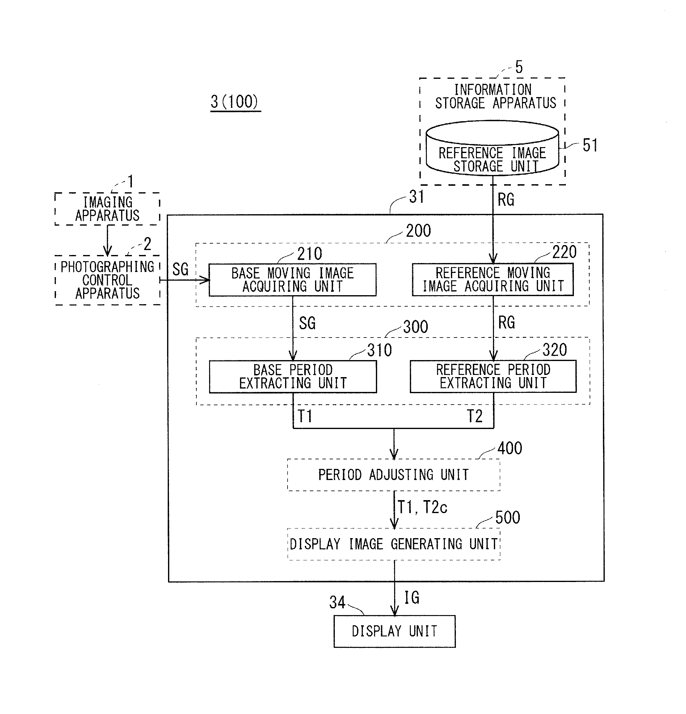
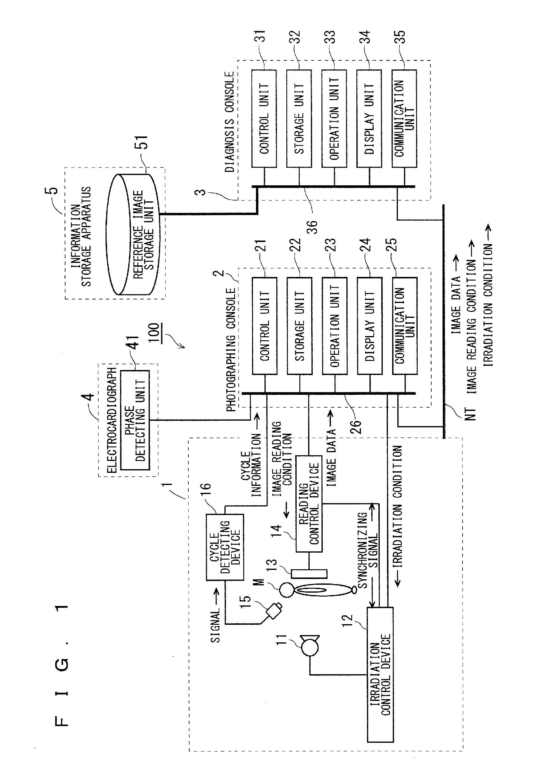
[0050]FIG. 1 is a diagram showing an overall configuration of the radiographic dynamic image photographing system according to Embodiment 1. As shown in FIG. 1, a radiographic dynamic image photographing system 100 includes an imaging apparatus 1, a photographing control apparatus 2 (photographing console), an image processing apparatus 3 (diagnosis console), and an electrocardiograph 4. The imaging apparatus 1 and the electrocardiograph 4 are connected with the photographing control apparatus 2 by a communication cable or the like, and t...

embodiment 2

2. Embodiment 2

[0185]FIG. 26 shows a functional configuration of a control unit 31A used in an image processing apparatus 3A configured as Embodiment 2 of the present invention. The control unit 31A is used as a substitute for the control unit 31 (see FIG. 6) in the image processing apparatus 3 in Embodiment 1. This embodiment differs from Embodiment 1 in that a period adjusting unit 400A that corresponds to the period adjusting unit 400 in Embodiment 1 further includes an adjustment target switching unit 450. The remaining configuration is similar to that of the image processing apparatus 3.

[0186]450>

[0187]The adjustment target switching unit 450 in the period adjusting unit 400A switches the respiratory cycle to be adjusted between the first respiratory cycle T1 and the second respiratory cycle T2. That is to say, in a case where the respiratory cycle to be adjusted before switching is the second respiratory cycle T2, the adjustment target switching unit 450 can switch the respira...

embodiment 3

3. Embodiment 3

[0198]FIG. 28 shows a functional configuration of a control unit 31B used in an image processing apparatus 3B configured as Embodiment 3 of the present invention. The control unit 31B is used as a substitute for the control unit 31 (see FIG. 6) in the image processing apparatus 3 in Embodiment 1. This embodiment differs from Embodiment 1 in that a period adjusting unit 400B that corresponds to the period adjusting unit 400 in Embodiment 1 further includes a period matching processing unit 460. The remaining configuration is similar to that of the image processing apparatus 3.

[0199]460>

[0200]The period matching processing unit 460 in the period adjusting unit 400B performs period matching processing of setting one of the first respiratory cycle T1 and the second respiratory cycle T2 as the respiratory cycle to be fixed, setting the other one of the first respiratory cycle T1 and the second respiratory cycle T2 as the respiratory cycle to be adjusted as a target for adj...


PUM


Abstract

An image processing apparatus includes: a base period extracting unit extracting a first target region period based on a first periodic change being a periodic change of a target region in a base moving image acquired by a base moving image acquiring unit; a reference period extracting unit extracting a second target region period based on a second periodic change being a periodic change of the target region in a reference moving image acquired by a reference moving image acquiring unit; a period adjusting unit performing period adjusting processing of synchronizing, for the first target region period or the second target region period, the first periodic change and the second periodic change with each other at a particular phase; and a display image generating unit generating a display image allowing for comparison between the base moving image and the reference moving image after the period adjusting processing is performed.

Description

TECHNICAL FIELD[0001]The present invention relates to image processing technology for displaying a moving image in which a target region of a human body or an animal body is photographed.BACKGROUND ART[0002]In medical settings, an affected part of a human body or the like in internal organs, skeletons, and the like is photographed, for example, with X-rays for various tests and diagnoses. Through application of recent digital technology, a moving image in which movement of an affected part is captured with X-rays or the like can be acquired relatively easily.[0003]In the recent digital technology, a dynamic image of a subject including a diagnosis target region can be photographed with use of a semiconductor imaging sensor such as a flat panel detector (FPD), enabling diagnosis through motion analysis of the diagnosis target region, which cannot be made in still image photographing and diagnosis by conventional X-ray photography.[0004]In making diagnosis with use of moving images, m...

Claims


Application Information

Patent Timeline
Patent Type & Authority Applications(United States)
IPC IPC(8): G06T7/00G06T11/60
CPCG06T7/0016G06T11/60G06T2207/30061G06T2207/10124G06T2210/41A61B6/461A61B6/5288A61B6/541
Inventor YAMATO, HIROSHISHIMAMURA, KENTATOYAMA, OSAMUMURAOKA, SHINTARONOJI, SHO
Owner KONICA MINOLTA INC
Why Eureka
Try Eureka