Image processing apparatus and image processing method
a technology of image processing and image processing apparatus, applied in the field of image processing technology, can solve the problem of difficult to simply compare a plurality of moving images, and achieve the effect of facilitating diagnosis and facilitating comparison
- Summary
- Abstract
- Description
- Claims
- Application Information
AI Technical Summary
Benefits of technology
Problems solved by technology
Method used
Image
Examples
embodiment 1
[0048]
[0049]A radiographic dynamic image photographing system according to Embodiment 1. of the present invention is described below.
[0050]
[0051]The radiographic dynamic image photographing system according to Embodiment 1. photographs a radiographic dynamic image of a target region of a subject that is a human body or an animal body. The target region includes, for example, lungs and a heart, and is a region whose state changes periodically.
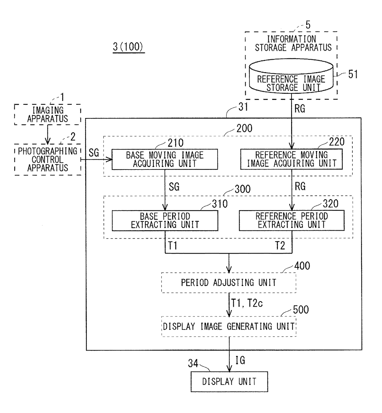
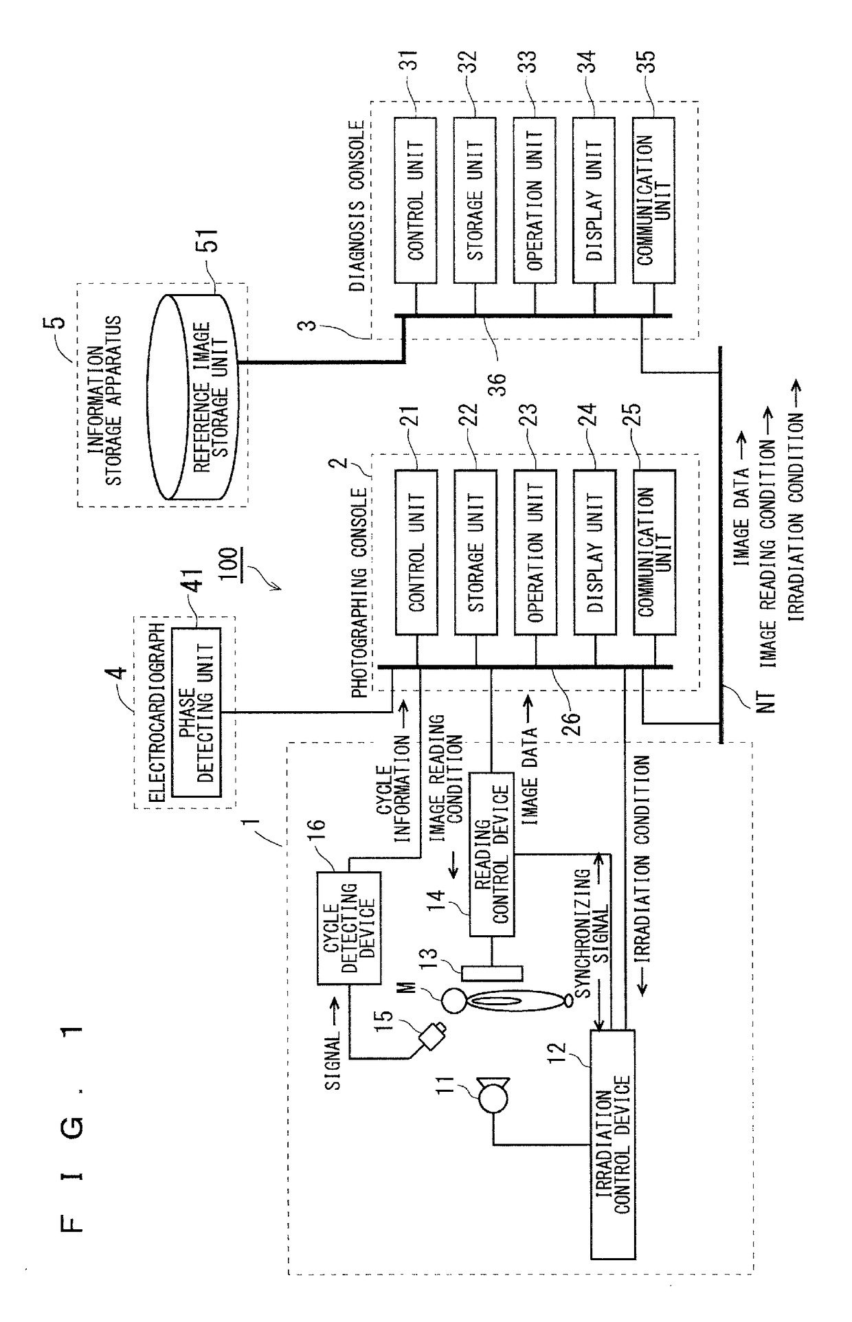
[0052]FIG. 1 is a diagram showing an overall configuration of the radiographic dynamic image photographing system according to Embodiment 1. As shown in FIG. 1, a radiographic dynamic image photographing system 100 includes an imaging apparatus 1, a photographing control apparatus 2 (photographing console), an image processing apparatus 3 (diagnosis console), and an electrocardiograph 4. The imaging apparatus 1 and the electrocardiograph 4 are connected with the photographing control apparatus 2 by a communication cable or the like, and the phot...
embodiment 2
[0186]
[0187]FIG. 26 shows a functional configuration of a control unit 31A used in an image processing apparatus 3A configured as Embodiment 2. of the present invention. The control unit 31A is used as a substitute for the control unit 31 (see FIG. 6) in the image processing apparatus 3 in Embodiment 1. This embodiment differs from Embodiment 1 in that a period adjusting unit 400A that corresponds to the period adjusting unit 400 in Embodiment 1. further includes an adjustment target switching unit 450. The remaining configuration is similar to that of the image processing apparatus 3.
[0188]450>
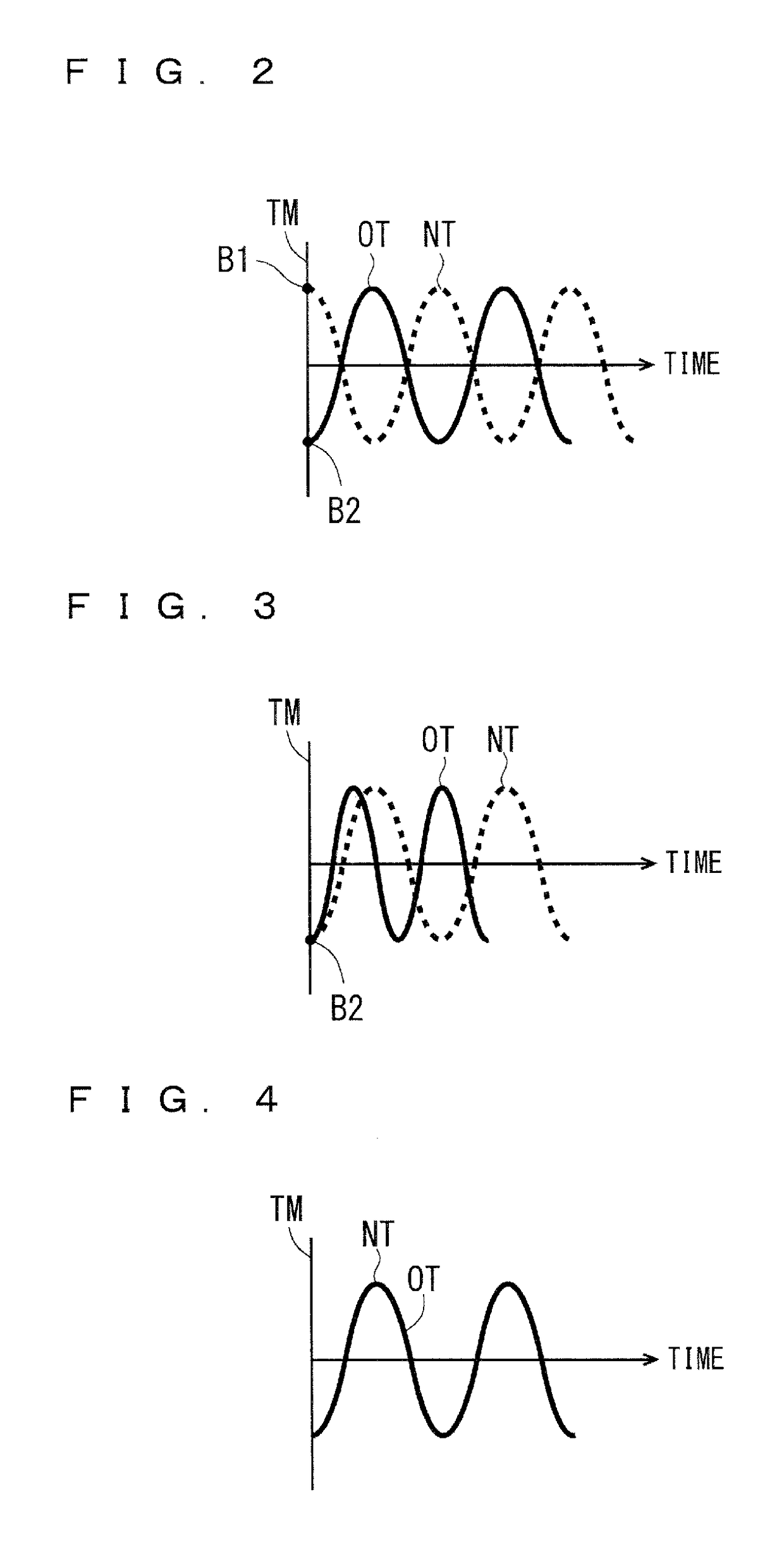
[0189]The adjustment target switching unit 450 in the period adjusting unit 400A switches the respiratory cycle to be adjusted between the first respiratory cycle T1 and the second respiratory cycle T2. That is to say, in a case where the respiratory cycle to be adjusted before switching is the second respiratory cycle T2, the adjustment target switching unit 450 can switch the respiratory cy...
embodiment 3
[0200]
[0201]FIG. 28 shows a functional configuration of a control unit 31B used in an image processing apparatus 3B configured as Embodiment 3. of the present invention. The control unit 31B is used as a substitute for the control unit 31 (see FIG. 6) in the image processing apparatus 3 in Embodiment 1. This embodiment differs from Embodiment 1 in that a period adjusting unit 400B that corresponds to the period adjusting unit 400 in Embodiment 1. further includes a period matching processing unit 460. The remaining configuration is similar to that of the image processing apparatus 3.
[0202]460>
[0203]The period matching processing unit 460 in the period adjusting unit 400B performs period matching processing of setting one of the first respiratory cycle T1 and the second respiratory cycle T2 as the respiratory cycle to be fixed, setting the other one of the first respiratory cycle T1 and the second respiratory cycle T2 as the respiratory cycle to be adjusted as a target for adjustment...
PUM
 Abstract
Description
Claims
Application Information
 - R&D
- Intellectual Property
- Life Sciences
- Materials
- Tech Scout
- Unparalleled Data Quality
- Higher Quality Content
- 60% Fewer Hallucinations
Browse by: Latest US Patents, China's latest patents, Technical Efficacy Thesaurus, Application Domain, Technology Topic, Popular Technical Reports.
© 2025 PatSnap. All rights reserved.Legal|Privacy policy|Modern Slavery Act Transparency Statement|Sitemap|About US| Contact US: help@patsnap.com


