Current sensing circuit for switching power converters

a current sensing circuit and power converter technology, applied in the direction of power conversion systems, dc-dc conversion, instruments, etc., can solve the problems of imbalanced current between phases, relative poor efficiency of linear power conversion systems, error voltage can interfere with accurate current sensing,

Active Publication Date: 2015-12-17
SEMICON COMPONENTS IND LLC
View PDF5 Cites 23 Cited by
  • Summary
  • Abstract
  • Description
  • Claims
  • Application Information

AI Technical Summary

Benefits of technology

[0049]It will be appreciated that some embodiments may be comprised of one or more generic or specialized processors (or “processing devices”) such as microprocessors, digital signal processors, customized processors and field programmable gate arrays (FPGAs) and unique stored program instructions (including both software and firmware) that control the one or more processors to implement, in conjunction with certain non-processor circui

Problems solved by technology

SMPSs are much preferred over linear power regulation, due to the relatively poor efficiency of linear power conversion systems.
The effect of circuit board conductors becomes especially of concern in multi-phase converters where the distances between the switching

Method used


Image

  • Current sensing circuit for switching power converters
  • Current sensing circuit for switching power converters
  • Current sensing circuit for switching power converters

Examples


Embodiment Construction

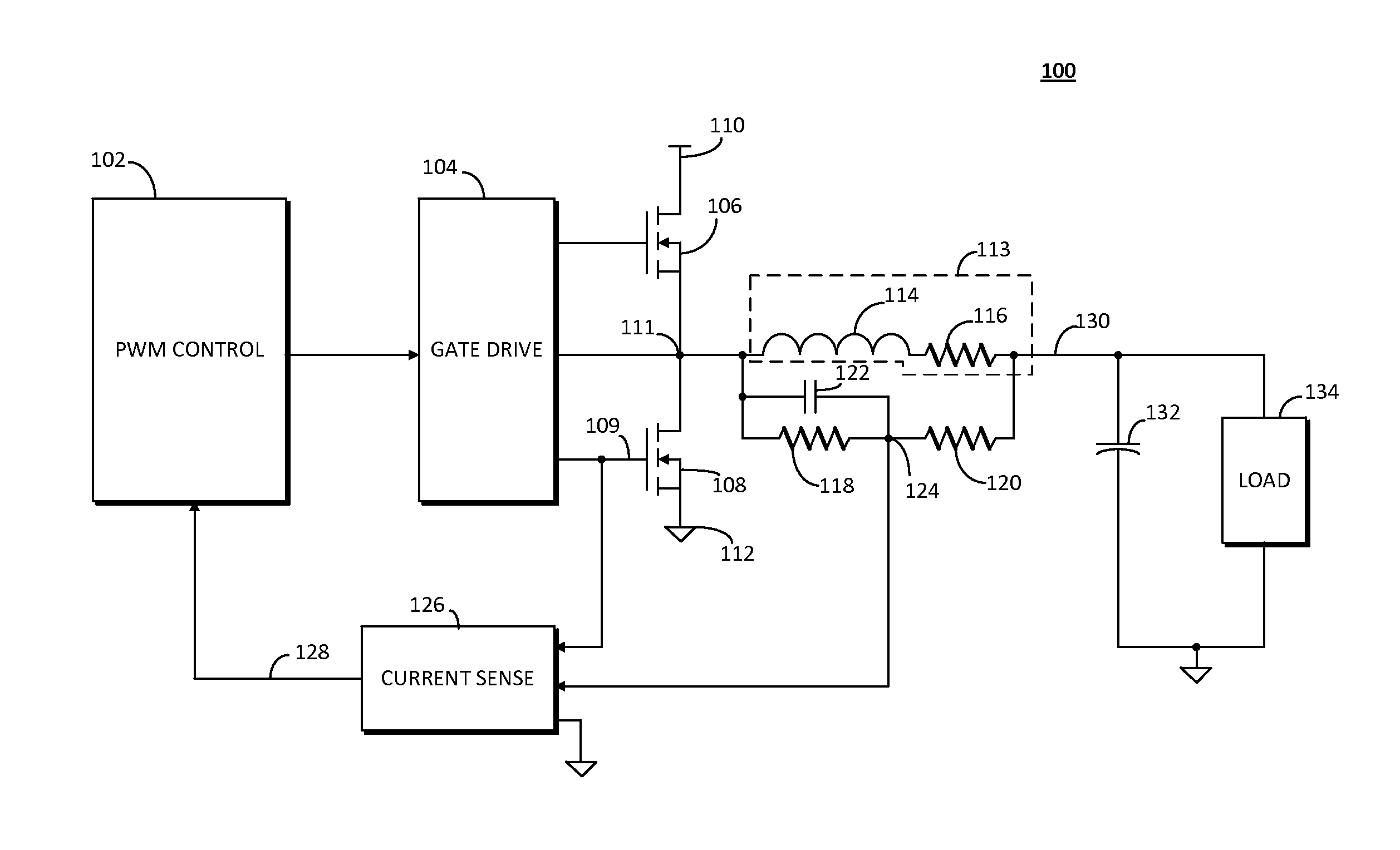
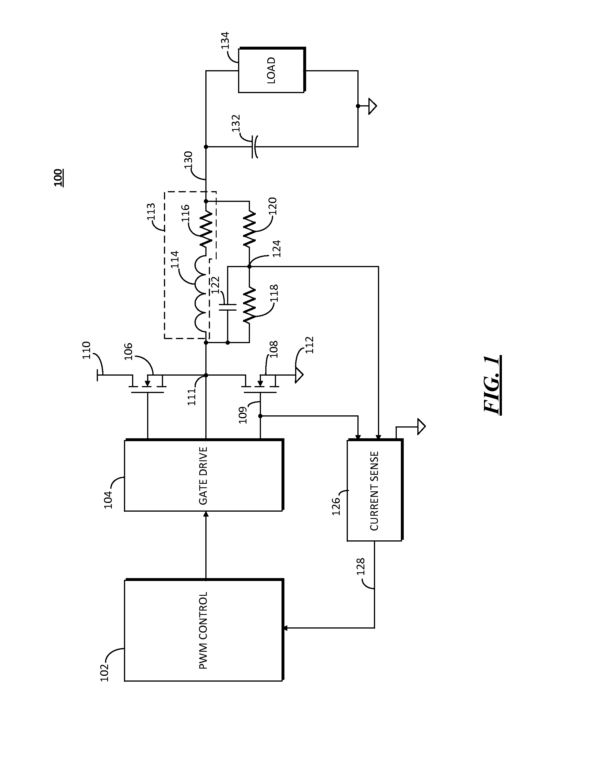
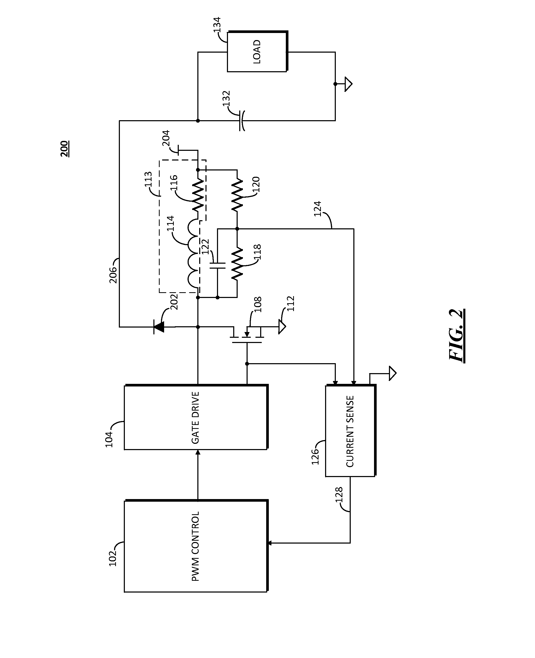
[0014]Embodiments disclosed herein include a current sensing circuit for a switched mode power converter that includes a first current sense resistance and a second current sense resistance coupled in series at a current sense node to form a series current sense resistance. The series current sense resistance is coupled in parallel with an inductor having an inductance and an inherent resistance, and a first end connected to a switching network. The switching network alternately connects and disconnects the inductor in series with a power source. When the switching network disconnects the inductor from the power source, current continues flowing through the inductor through another path, which can also be part of the switching network. The first current sense resistance is coupled to the first end of the inductor, and the second current sense resistance is coupled to a second end of the inductor. A capacitance is coupled in parallel with the first current sense resistance.

[0015]FIG....


PUM


Abstract

A current sensing circuit for a switched mode power converter employs a passive current sensing network coupled in parallel with the switched inductor. The passive current sensing network is impedance matched to the inductance its inherent resistance, and provides a current sensing node for single wire current sensing by a current sensing circuit. The passive current sensing network can be employed in each of a plurality of phased switching circuits that each contribute to an output of the power converter.

Description

FIELD OF THE DISCLOSURE[0001]The present disclosure relates generally to power regulation circuits, and particularly to current sensing in switched-mode power converters.BACKGROUND[0002]A switched-mode power supply (SMPS) utilizes energy storage in the magnetic field of an inductance, coupled with switching action from a supply source, to regulate an output voltage, current, or electric power. SMPSs are much preferred over linear power regulation, due to the relatively poor efficiency of linear power conversion systems. Simple SMPSs of early designs often used a diode for flywheel conduction when the switch connecting the magnetizing inductance to the source is switched off In improving the efficiency of SMPSs, however, conduction diodes have been replaced by switching transistors such as metallic-oxide semiconductor field effect transistors (MOSFETs), or insulated gate field effect transistors (IGFET), which are synchronously switched to provide the necessary blocking and conductio...

Claims


Application Information

Patent Timeline
IPC IPC(8): H02M3/158H02M1/00
CPCH02M3/158H02M3/1584H02M1/0009H02M3/1586H02M3/156
Inventor CHEN, GANG
Owner SEMICON COMPONENTS IND LLC
Why Eureka
Try Eureka