Internal cam metering pump

a technology of internal cam and metering pump, which is applied in the direction of piston pump, positive displacement liquid engine, instrument, etc., can solve the problems of inability to use flexible reservoirs, and relatively complex embodiments

Active Publication Date: 2016-01-07
BECTON DICKINSON & CO
View PDF0 Cites 41 Cited by
  • Summary
  • Abstract
  • Description
  • Claims
  • Application Information

AI Technical Summary

Problems solved by technology

However, these embodiments are relatively complex and not cost effective.
Thus it is impossi

Method used


Image

  • Internal cam metering pump
  • Internal cam metering pump
  • Internal cam metering pump

Examples


Embodiment Construction

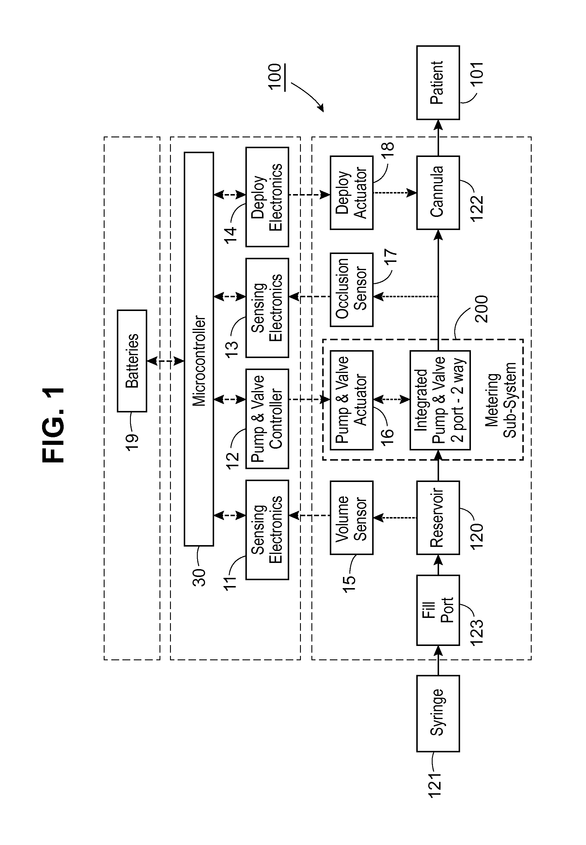
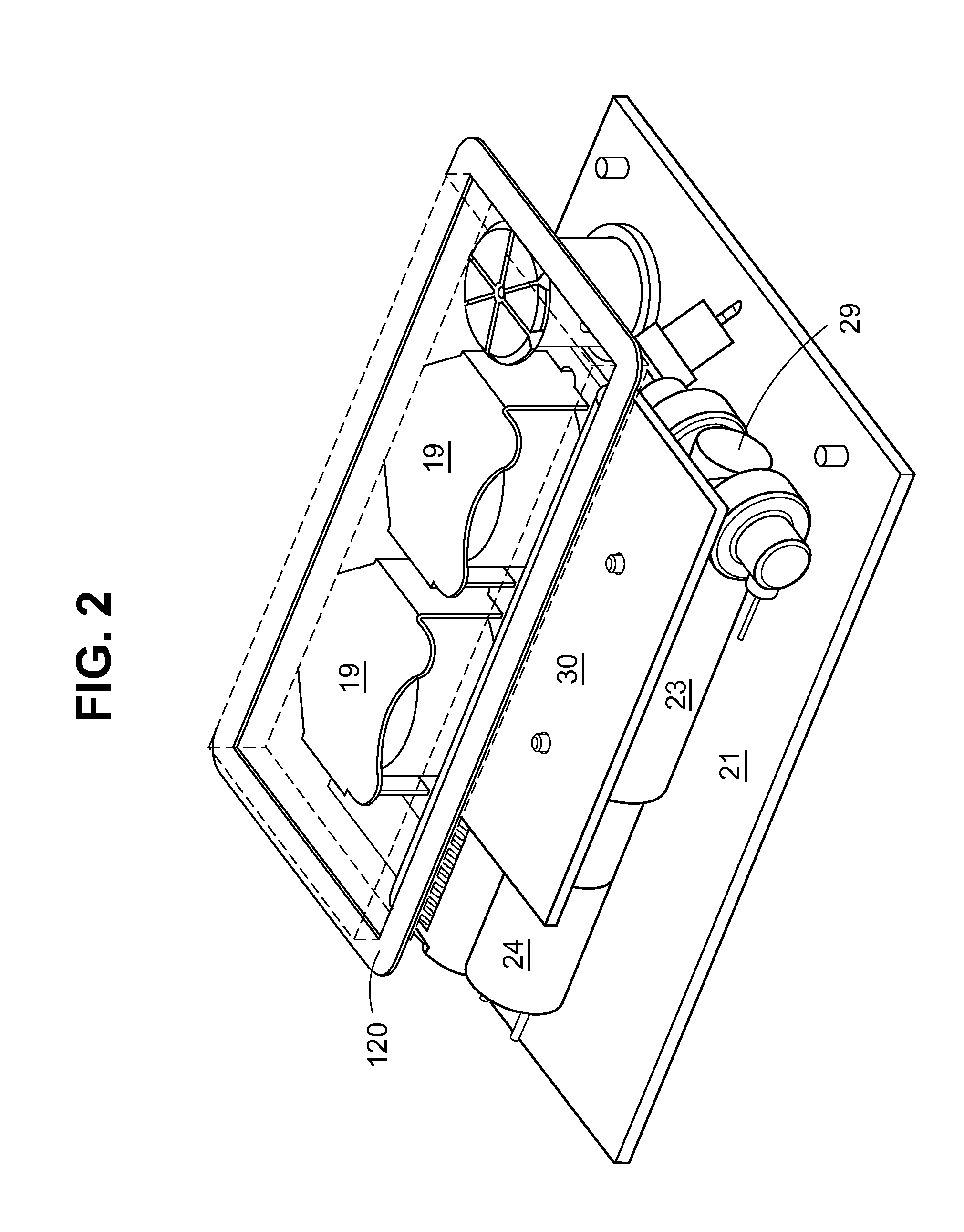
[0021]FIG. 1 provides a schematic overview of a fluid delivery system 100, comprising a reservoir 120 in fluid communication with metering subsystem 200 for drawing a precise amount of fluid from the reservoir. A cannula mechanism 122 is provided for delivering medication from the metering subsystem 200 to the user 101. The fluid delivery system, including metering subsystem 200, is preferably lightweight and wearable and assembled in a compact form as shown in FIG. 2, so that the elements may be included in a single housing. The cannula mechanism 122 may be connected to the infusion site by an infusion set comprising tubing and a patch, or alternatively a cannula insertion mechanism may be incorporated into the housing along with the metering subsystem 200.

[0022]In embodiments, the pump is adapted to provide a continuous infusion dosage over 1 to 5 days. For example, in the case of insulin infusion, the pump may be worn and disposed of after 84 hours and the reservoir is sized to p...


PUM


Abstract

A micropump according to the invention uses an eccentric cam member rotating within a pump housing to sequentially open and close valves in the pump housing to withdraw fluid from a reservoir and provide metered amounts of the fluid to a cannula port for administration to a patient. The micropump may be used in a disposable pump for continuous infusion of medication such as insulin.

Description

BACKGROUND OF THE INVENTION[0001]1. Field of the Invention[0002]The present invention is directed to a micropump adapted for the continuous delivery of a liquid medication by infusion such as may be used in the delivery of insulin for the treatment of diabetes.[0003]2. Description of the Related Art[0004]Micropumps for the subcutaneous delivery of drugs are known, for example, from U.S. Pat. Nos. 7,726,955 and 8,282,366. This prior art describes, in various embodiments, a pump having a rotor mounted in a stator, or housing. Sealing rings situated at an angle on axial extensions on the rotor cooperate with channels formed between the rotor and the stator to move liquid in precise amounts through a rotor housing. However, these embodiments are relatively complex and not cost effective. The user keeps the pump when the infusion patch is changed, for several weeks. As the art continues to evolve toward fully disposable pumps, the need for compact and economical micropump designs remains...

Claims


Application Information

Patent Timeline
IPC IPC(8): A61M5/168
CPCA61M5/16831A61M5/1413A61M5/14216A61M2005/16863A61M2205/103A61M2005/14252A61M5/14244F04B19/025F04B49/16F04B43/043F04B7/06F04B7/04F04B7/0065F04B9/042F04B19/006F04B39/08F04B7/0057F04B9/047
Inventor FOCHT, KENNETHGORDON, JOSEPHFISK, JUSTINPERRY, MATTHEW J.
Owner BECTON DICKINSON & CO
Why Eureka
Try Eureka