Multi-Touch Interface for Blind Real-Time Interaction

a multi-touch interface and real-time interaction technology, applied in the direction of user-computer interaction input/output, instruments, electric digital data processing, etc., can solve the problems of cluttered interface, bending and modulation wheels can only control one parameter each, and affecting the effect of user experien

Inactive Publication Date: 2016-01-14
WALTHER THOMAS CHRISTIAN
View PDF0 Cites 12 Cited by
  • Summary
  • Abstract
  • Description
  • Claims
  • Application Information

AI Technical Summary

Benefits of technology

[0015]In conclusion, insofar as I am aware, no control interface formerly developed provides the user an input method that allows him or her to con

Problems solved by technology

Some users know the position of knobs, faders and other input devices on a machine by heart, but this requires extensive training With an increasing number of faders, knobs or similar control elements, reaching for the right control becomes more difficult.
Also, said pitch bend and modulation wheels can only control one parameter each.
While they are easy to reach blindly by users while performing, if manufacturers were to add more wheels, the interface would get cluttered and a user could not find the right wheel easily anymore.
Furthermore, it requires precise aiming at interface e

Method used


Image

  • Multi-Touch Interface for Blind Real-Time Interaction
  • Multi-Touch Interface for Blind Real-Time Interaction
  • Multi-Touch Interface for Blind Real-Time Interaction

Examples


Embodiment Construction

[0022]The various aspects will be described in detail with reference to the accompanying figures. Wherever possible, the same reference numbers will be used throughout the drawings to refer to the same or like parts. References made to particular examples and implementations are for illustrative purposes and are not intended to limit the scope of the invention or the claims.

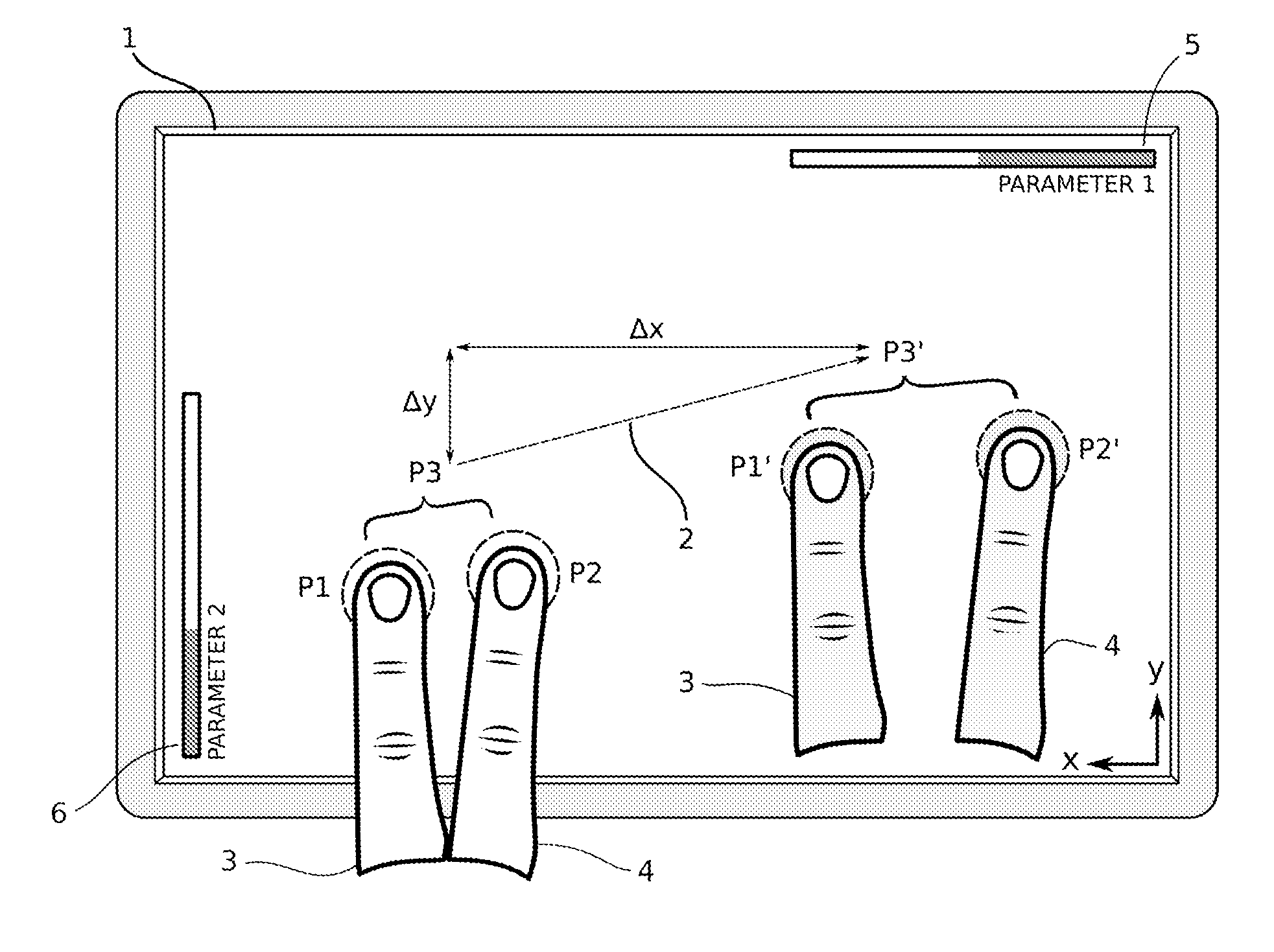
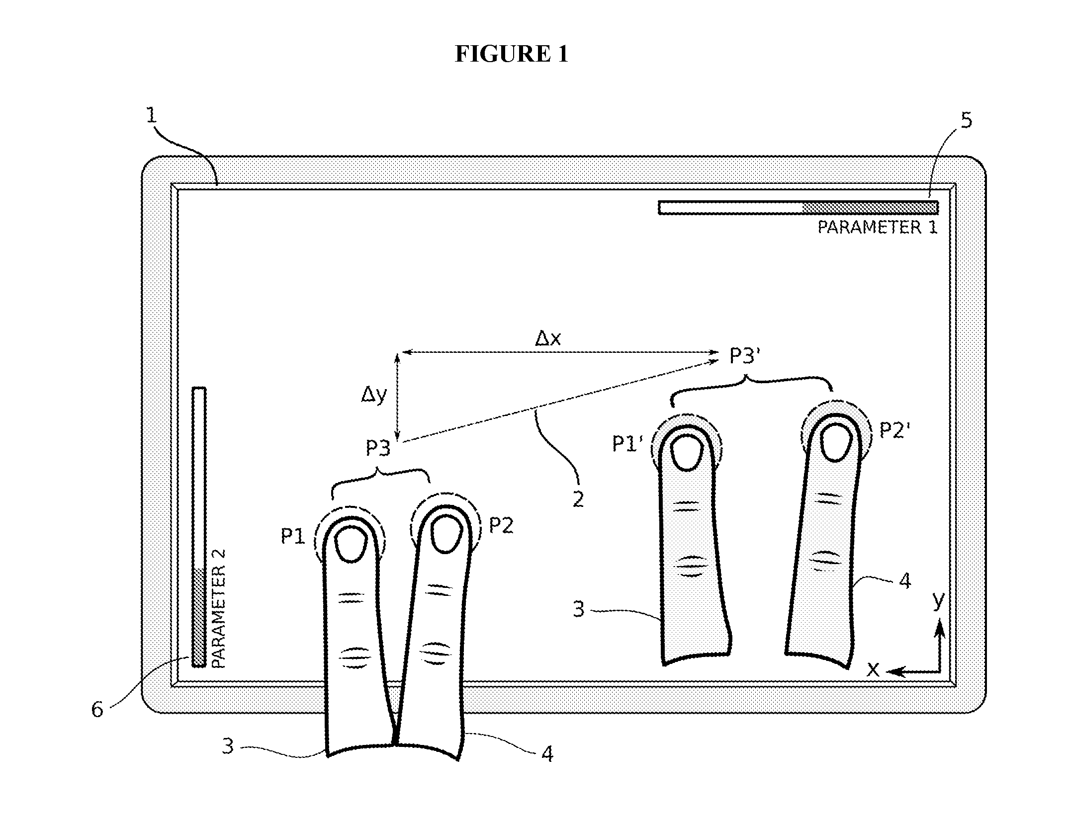
[0023]FIG. 1 is a top-down view on a touch area, taken from the user's point of view. It shows a touch area (in further context also described as touch surface, or surface) that is surrounded by a frame. The touch area is not divided into subsections, but acts equally wherever the user touches it. Two fingers 3 and 4 of a user's hand touch the surface at positions P1 and P2. The fingers 3 and 4 move to another position P1′ and P2′. The average positions of P1 and P2, and P1′ and P2′, are illustrated as P3, or P3′ respectively. The movement is illustrated by arrow 2, which points from P3 to P3′. The arrow 2 is div...


PUM


Abstract

Apparatus and methods are disclosed for controlling multiple parameters on a multi-touch surface. Design of the apparatus and the multi-touch gestures enable unprecedented control of parameters by allowing the user to alter multiple parameters blindly in real-time with varying sensitivity.

Description

CROSS-REFERENCE TO RELATED APPLICATIONS[0001]This application claims the benefit of the provisional patent application Ser. No. 61 / 845,941, filed 2013 Jul. 11 by the present inventor.BACKGROUNDPrior Art[0002]The following is a tabulation of some prior art that presently appears relevant:U.S. Patent Application PublicationsPublication Nr.Kind CodePubl. DateApplicantU.S. Pat. No. 4,179,971ADec. 25, 1979Nippon Gakki Seizo Kabushiki KaishaU.S. Pat. No. 5,741,993AApr. 21, 1998Kabushiki Kaisha Kawai Gakki SeisakushoNonpatent Literature Documents[0003]Korg Kaoss Pad KP2 Owner's Manual. 2002.[0004]Korg Kaoss Pad KP3+ Website; Accessed Jul. 9, 2014.[0005]JazzMutant Lemur Website, Accessed Jul. 9, 2014. jazzmutant.com / lemur_overview.php[0006]Moog Minimoog Voyager XL Owner's Manual. 2010.[0007]The present invention relates to interfaces in general, and specifically touch interfaces, that allow users to change parameters of a software or a hardware device, either integrated or attached to the e...

Claims


Application Information

Patent Timeline
IPC IPC(8): G06F3/041G06F3/01G06F3/0484G06F3/0488
CPCG06F3/0418G06F3/04847G06F2203/04808G06F3/016G06F3/0488
Inventor WALTHER, THOMAS, CHRISTIAN
Owner WALTHER THOMAS CHRISTIAN
Why Eureka
Try Eureka