Spring contact, inertia switch, and method of manufacturing an inertia switch

a technology of inertia switch and spring contact, which is applied in the direction of selector switch, contact, electrical apparatus, etc., can solve the problems of deformation of the spring contact, adversely affecting the function of the switch, etc., to reduce or eliminate chatter, reduce or eliminate deformation

Active Publication Date: 2016-02-18
CIRCOR AEROSPACE
View PDF5 Cites 6 Cited by
  • Summary
  • Abstract
  • Description
  • Claims
  • Application Information

AI Technical Summary

Benefits of technology

[0012]Another advantage is that decreasing or eliminating the deformation of the spring contact of the present invention provides increased performance reliability.
[0013]Yet another advantage of the spring contact of the present invention is that a predetermined geometry of the break-off tab decreases particulate formation during insertion of the spring contact within the mass.
[0014]Still another advantage is that compressing the spring contact to decrease a size of the split during insertion generates a radially outward force a

Problems solved by technology

However, the interference fit causes undue stress on the thin spring contact which results in various deformations, adversely affecting the function of the switch.
Additionally, current mass-spring systems utilize a manually-operated arbor tool to press the flat spring contact into the mass, which results in deformation to the spring contact from the high forces required to overcome the interference between the spring contact and the mass.
This deformation may cause dimensional changes to the interface betwee

Method used


Image

  • Spring contact, inertia switch, and method of manufacturing an inertia switch
  • Spring contact, inertia switch, and method of manufacturing an inertia switch
  • Spring contact, inertia switch, and method of manufacturing an inertia switch

Examples


Embodiment Construction

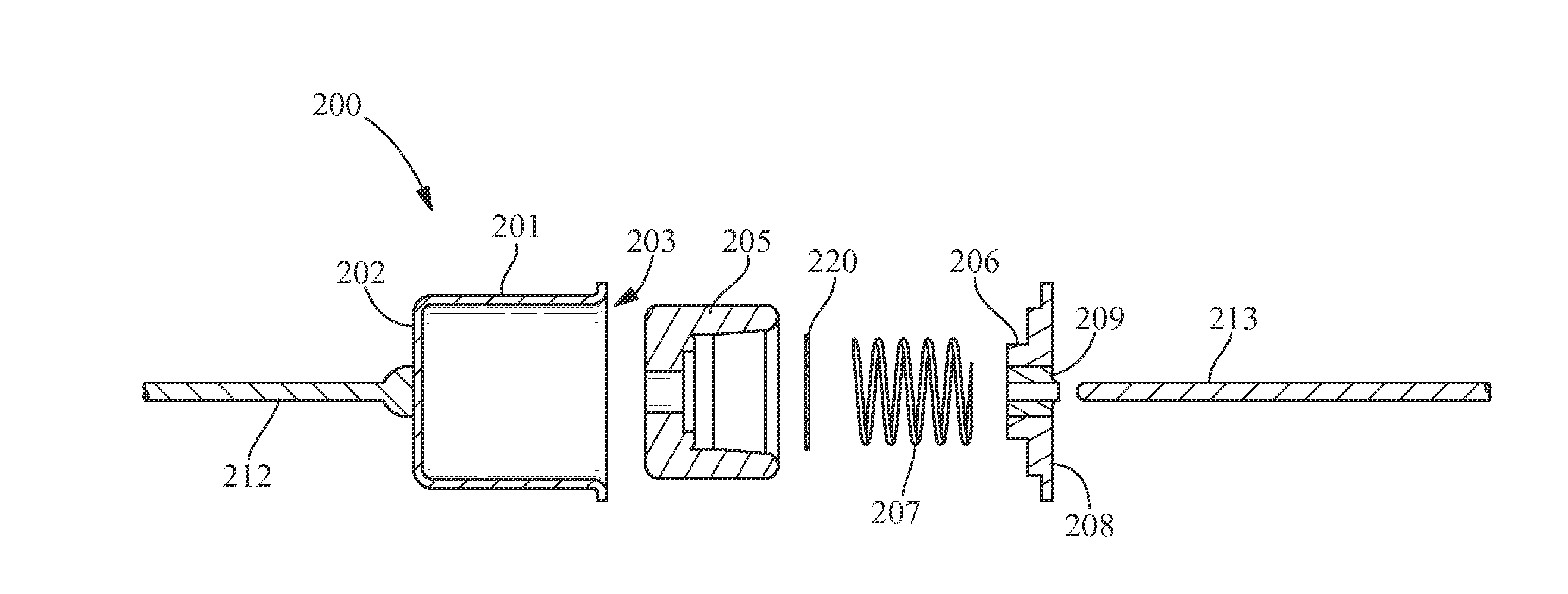
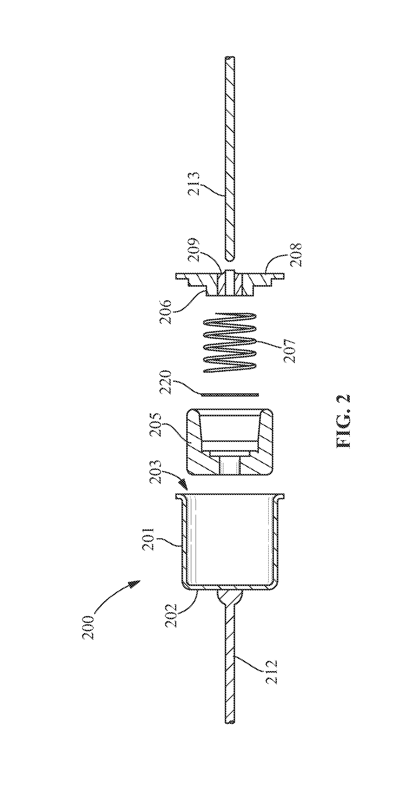
[0028]Referring to FIGS. 2-5, an inertia switch 200 includes any switch that is opened and / or closed by lateral or axial forces, such as, but not limited to, an acceleration switch, a miniature acceleration switch, an impact switch, any switch requiring chatter-proof contact (e.g., a chatter-proof miniature acceleration switch, an impact switch requiring little or no contact bounce), or a combination thereof. In one embodiment, the inertia switch 200 includes a shell 201 having a first end 202 and a second end 203. In another embodiment, the shell 201 is hollow, with the first end 202 being closed and the second end 203 being open. A first conductive member 212 is secured to the closed first end 202 by any suitable method for making an electrical connection, such as, but not limited to brazing, soldering, percussive welding, spot welding and the like.

[0029]The second end 203 is sealed with a cover assembly, such as a header 208. The header 208 is secured to the second end 203 by any...


PUM


Abstract

A spring contact, an inertia switch, and a method of manufacturing an inertia switch are provided. The spring contact includes a conductive body portion having an outer edge and an inner edge partially surrounding an open area, a split in the conductive body portion, the split extending between the outer edge and the inner edge, and a conductive contact finger extending from the inner edge into the open area. The inertia switch includes a shell; a mass movably positioned within the shell; the spring contact positioned within the mass; a biasing member positioned between the spring contact and the header; and a conductive member extending through the header. The biasing member provides a bias between the spring contact within the mass and the conductive member. The method includes at least partially closing the split in the spring contact during insertion of the spring contact within the mass.

Description

FIELD OF THE INVENTION[0001]The present invention is directed to a spring contact, an inertia switch, and a method of manufacturing an inertia switch. More specifically, the present invention is directed to a split spring contact in an inertia switch, and a method of manufacturing an inertia switch including a split spring contact.BACKGROUND OF THE INVENTION[0002]Inertia switches provide a means for detecting changes in axial or lateral forces. Some currently available inertia switch includes acceleration switches, which, as the name implies, are responsive to acceleration. Typically, an acceleration switch includes a system whereby a mass moves relative to an internal sensing element in response to acceleration.[0003]One specific type of acceleration switch includes a mass-spring system having a mass with a flat spring contact secured thereto, the mass being biased in an open or closed position with respect to a conductive lead wire. The mass may be biased through use of a spring t...

Claims


Application Information

Patent Timeline
IPC IPC(8): H01H35/14H01H11/04
CPCH01H35/141H01H11/04H01H35/145H01H9/04
Inventor GASS, DAVIDSALAMONE, BRENTJORDAN, COREY C.
Owner CIRCOR AEROSPACE
Why Eureka
Try Eureka