

Folding assemblies with locking mechanism
- Summary
- Abstract
- Description
- Claims
- Application Information
AI Technical Summary
Benefits of technology
Problems solved by technology
Method used
Image

Examples
Embodiment Construction
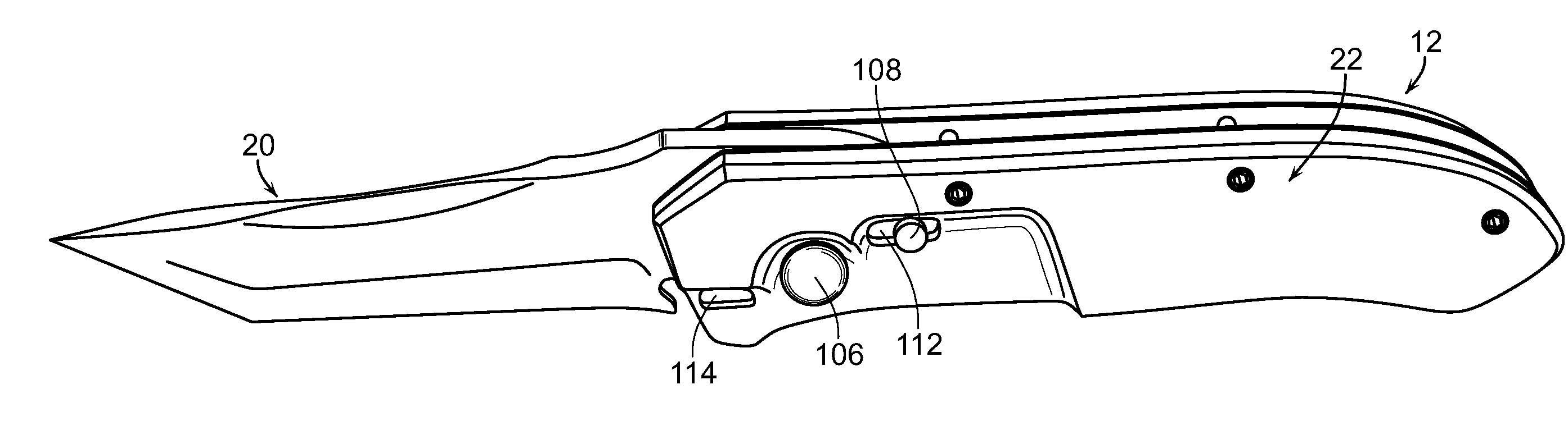
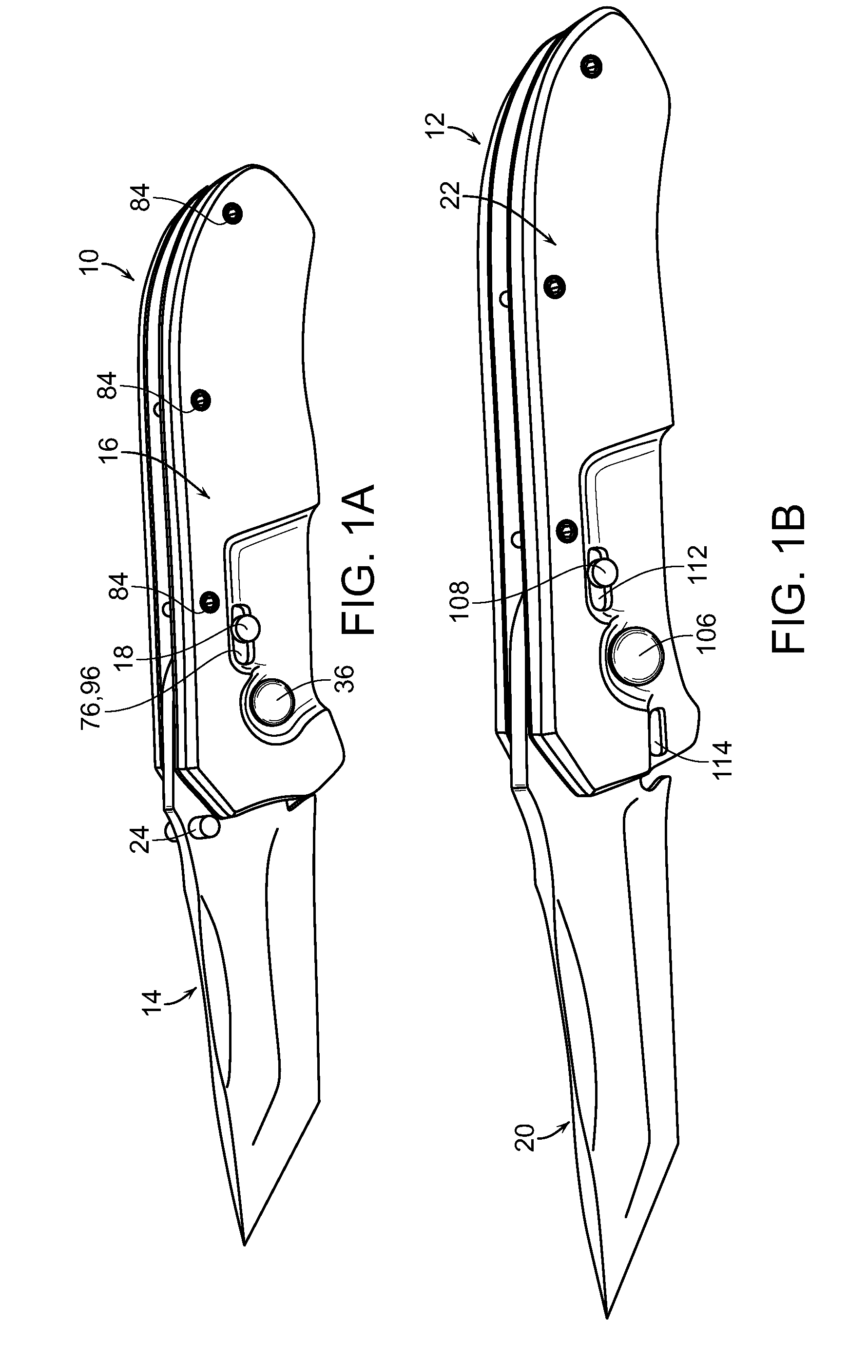
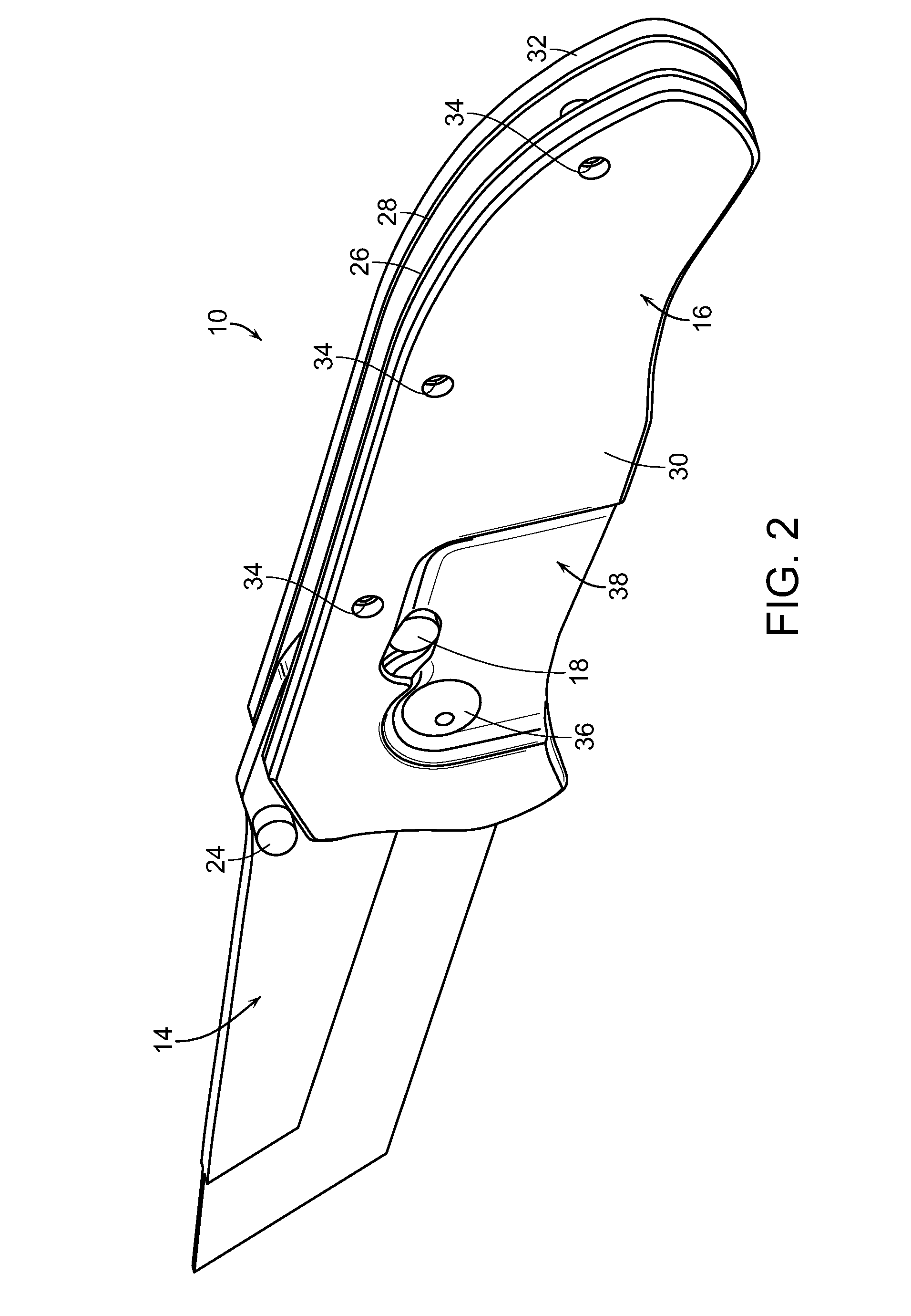
[0031]As shown in the accompanying drawings, for purposes of illustration, the present invention resides in folding assemblies having one member that is pivotally attached to another member, and incorporating a locking mechanism for fixing the location of the one member relative to the other, such as in an open and / or closed position.
[0032]Generally, folding assemblies with locking mechanisms as disclosed herein comprise first and second members that are pivotably attached to one another and include an improved locking mechanism when contrasted to conventional folding assemblies with locking mechanisms such as those described above known in the art. More specifically, folding assemblies and locking mechanisms as disclosed herein comprise a first member that is pivotably attached to a second member, wherein the first member is interposed between a pair of liners that are part of the second member. Each of the liners are specially configured to accommodate and enable rotational moveme...
PUM
 Abstract
Description
Claims
Application Information