Tensioner for Engine with Large and Stable Damping and Minimum Deflection o f Shaft

a technology of shaft deflection and a large damping, which is applied in the direction of belts/chains/gearings, mechanical equipment, belts/chains/gearings, etc., can solve the problems of large amount of frictional damping force generated, and achieve the effect of small shaft deflection, large and stable significant damping effect, and low deflection

Active Publication Date: 2016-10-06
NINGBO FENGMAO FAR EAST RUBBER
View PDF36 Cites 1 Cited by
  • Summary
  • Abstract
  • Description
  • Claims
  • Application Information

AI Technical Summary

Benefits of technology

[0010]A main object of the present invention is to provide a tensioner for engines, wherein the tensioner can provide a large and stable significant dampi

Problems solved by technology

Due to that the first and second positive tensions are generated at t

Method used


Image

  • Tensioner for Engine with Large and Stable Damping and Minimum Deflection o f Shaft
  • Tensioner for Engine with Large and Stable Damping and Minimum Deflection o f Shaft
  • Tensioner for Engine with Large and Stable Damping and Minimum Deflection o f Shaft

Examples


Embodiment Construction

[0040]The following description is disclosed to enable any person skilled in the art to make and use the present invention. Preferred embodiments are provided in the following description only as examples and modifications will be apparent to those skilled in the art. The general principles defined in the following description would be applied to other embodiments, alternatives, modifications, equivalents, and applications without departing from the spirit and scope of the present invention.

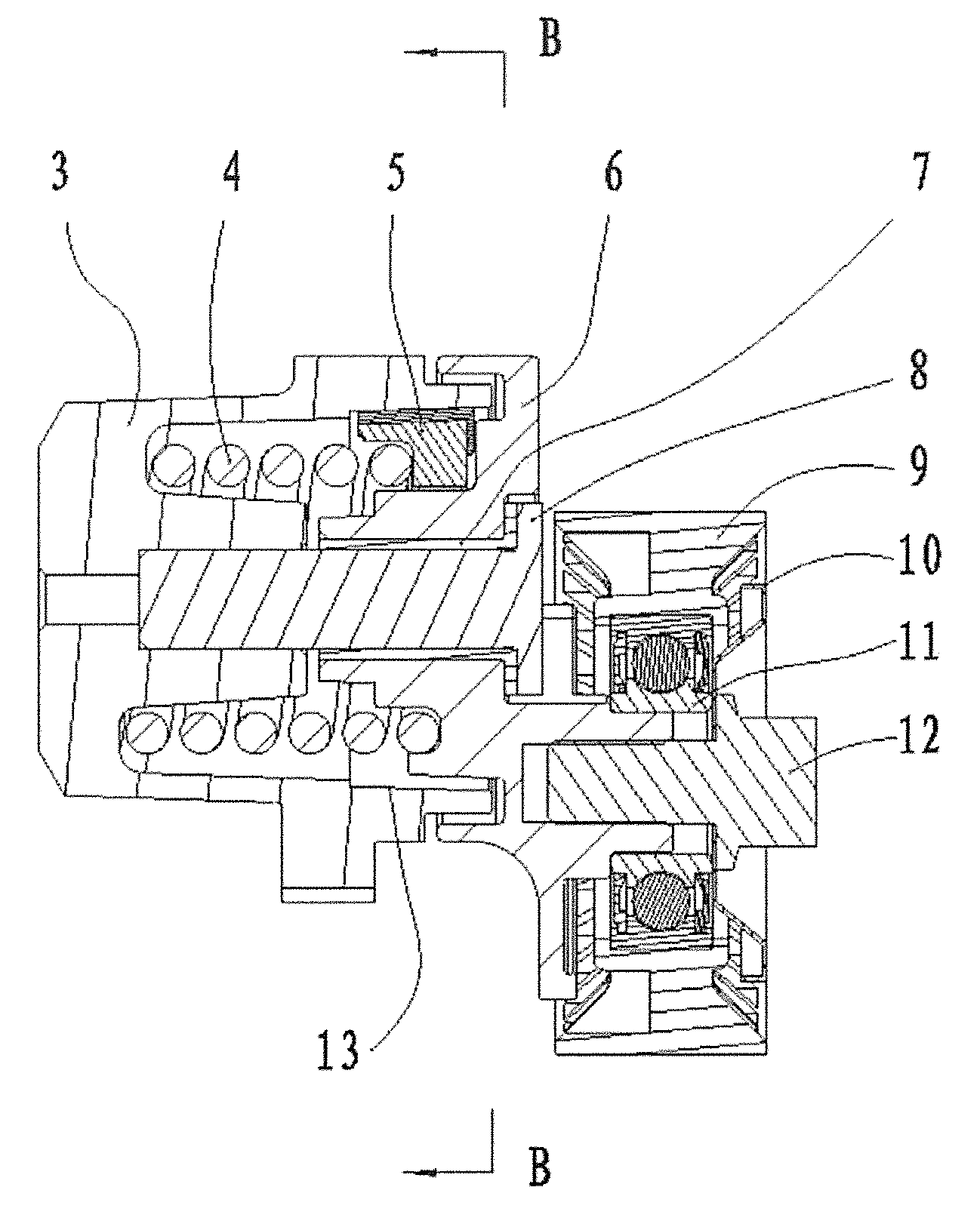
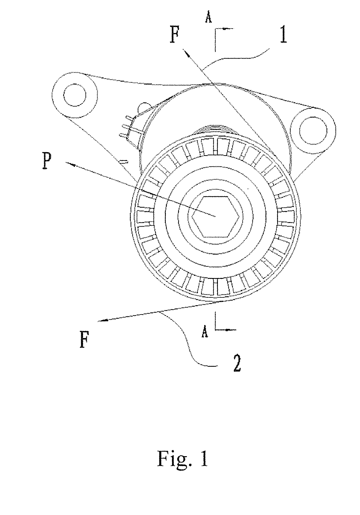
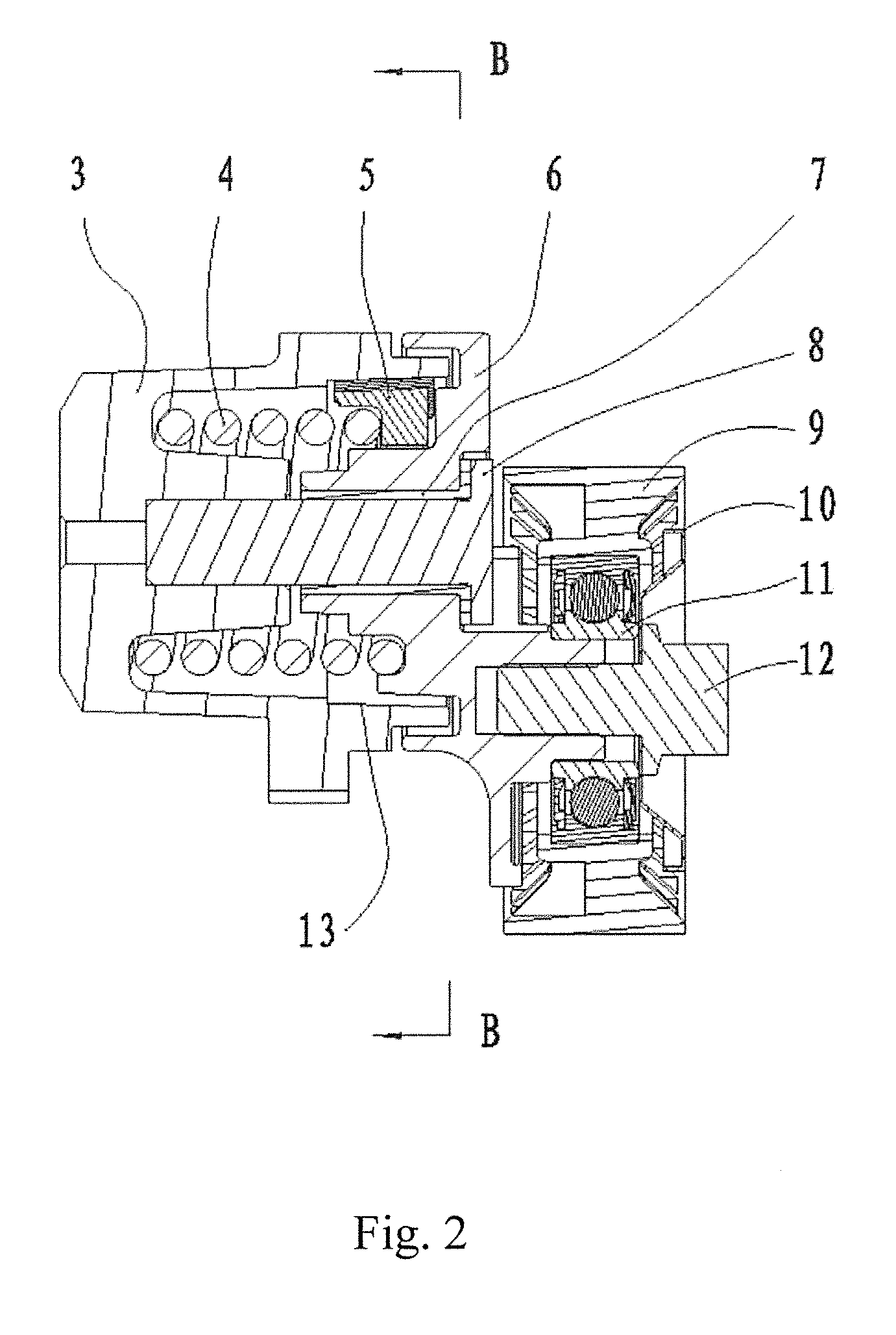
[0041]Referring to FIG. 1 and FIG. 2 of the drawings, a large damping and low attenuation tensioner for engines according to a preferred embodiment of the present invention, wherein the tensioner comprises a base 3, a retention arrangement 8 serving as a core shaft, a tension arrangement 6, an elastic member 4 disposed within the base 3 in a non-rotatably movable manner, and a damping member 5, such as a damping shoe, arranged inside the base 3, wherein the elastic member 4 is arranged to bias ag...


PUM


Abstract

A tensioner includes a base, a tension arrangement rotatable at the base, a damping member being rotated in a loading direction by the tension arrangement, and an elastic member biasing against the damping member. The position of the damping member depends by the layout geometry of the specific application and is directly in opposition to the hub load. The reaction force of the cylindrical surface of the base on the damping member is very near to the plan of the external forces represented by the hub load to minimize the deflection of the shaft. The tension arrangement is rotated to push the damping member for generating a first positive tension between the damping member and the base, and to expand the elastic member radially for generating a second positive tension between the elastic member and the damping member, so as to enhance a damping force of the tensioner.

Description

CROSS REFERENCE OF RELATED APPLICATION[0001]This is a Divisional application that claims priority to U.S. non-provisional application, application Ser. No. 14 / 621,333, filed Feb. 12, 2015, the entire contents of each of which are expressly incorporated herein by reference.NOTICE OF COPYRIGHT[0002]A portion of the disclosure of this patent document contains material which is subject to copyright protection. The copyright owner has no objection to any reproduction by anyone of the patent disclosure, as it appears in the United States Patent and Trademark Office patent files or records, but otherwise reserves all copyright rights whatsoever.BACKGROUND OF THE PRESENT INVENTION[0003]1. Field of Invention[0004]The present invention relates to a tensioner for engines, and more particularly to a tensioner for an engine with large and stable damping and minimum deflection of the shaft.[0005]2. Description of Related Arts[0006]Endless transmission device, such as belt drive or chain drive, is...

Claims


Application Information

Patent Timeline
IPC IPC(8): F16H7/12F16H7/08
CPCF16H7/1218F16H7/0831F16H2007/0893F16H2007/0865F16H2007/081
Inventor JIANG, CHUNLEIYANG, KE
Owner NINGBO FENGMAO FAR EAST RUBBER
Why Eureka
Try Eureka