
Valve for vacuum process

a vacuum process and valve technology, applied in the direction of spindle sealing, functional valve types, valve operating means/releasing devices, etc., can solve the problems of serious pump problems and reduce the life of the device, and achieve the effect of reducing the deposition of foreign materials

Active Publication Date: 2014-05-06
LEE DONG MIN
View PDF17 Cites 3 Cited by
  • Summary
  • Abstract
  • Description
  • Claims
  • Application Information

AI Technical Summary

Benefits of technology

The design effectively prevents foreign material deposition on the bellows and reduces shaft deflection, enhancing the stability and durability of vacuum system valves, thereby improving the longevity and performance of semiconductor manufacturing equipment.

Problems solved by technology

Accordingly, foreign materials are deposited inside the valves due to corrosive gas which may reduce a life time of the device and even cause a serious problem to the pump.

Method used


Image

  • Valve for vacuum process
  • Valve for vacuum process
  • Valve for vacuum process

Examples


Embodiment Construction

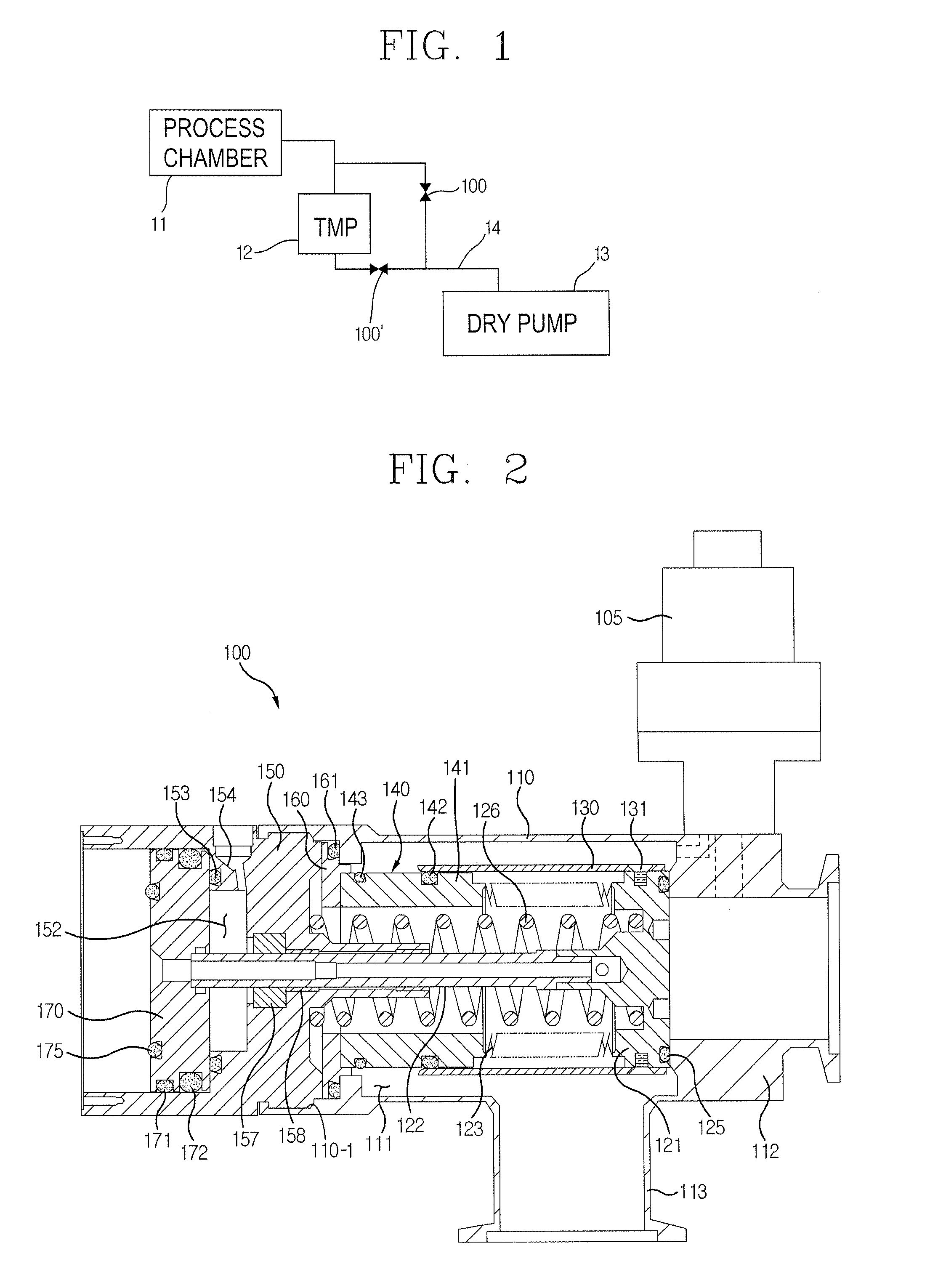
[0030]Hereinafter, a valve for vacuum process according to an exemplary embodiment will be described in detail with reference to accompanying drawings.

[0031]FIG. 1 is a schematic block diagram of a vacuum system that a valve for vacuum process according to an exemplary embodiment is used. FIG. 1 shows a process chamber 11, a turbo molecular pump (TMP) 12 and a dry pump 13.

[0032]When energy is provided to gas in a chamber to get a plasma state, a reaction occurs in a wafer in the chamber and a thin film is formed on the wafer. Unnecessary reactants generated in the thin film forming process are discharged through the turbo molecular pump 12 and a pipe 14. A first valve 100 for vacuum process is installed between the process chamber 11 and the dry pump 13. A second valve 100′ for vacuum process is installed at a downstream of the turbo pump. The first valve for vacuum process 100 may be also called ‘an isolation valve’. The second valve for vacuum process 100′ disposed at the downstre...


PUM


Abstract

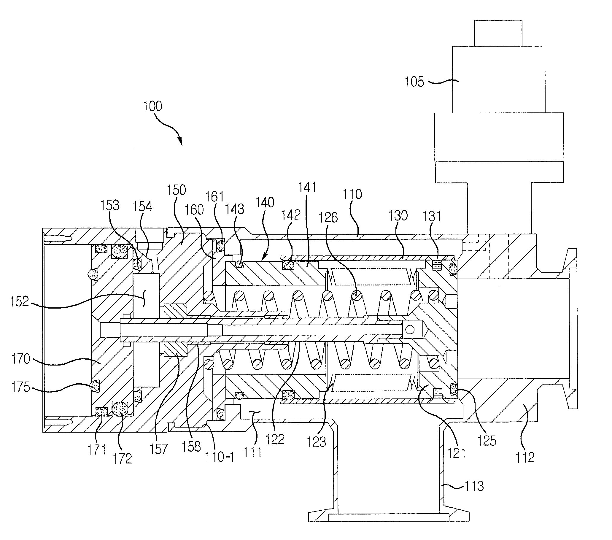
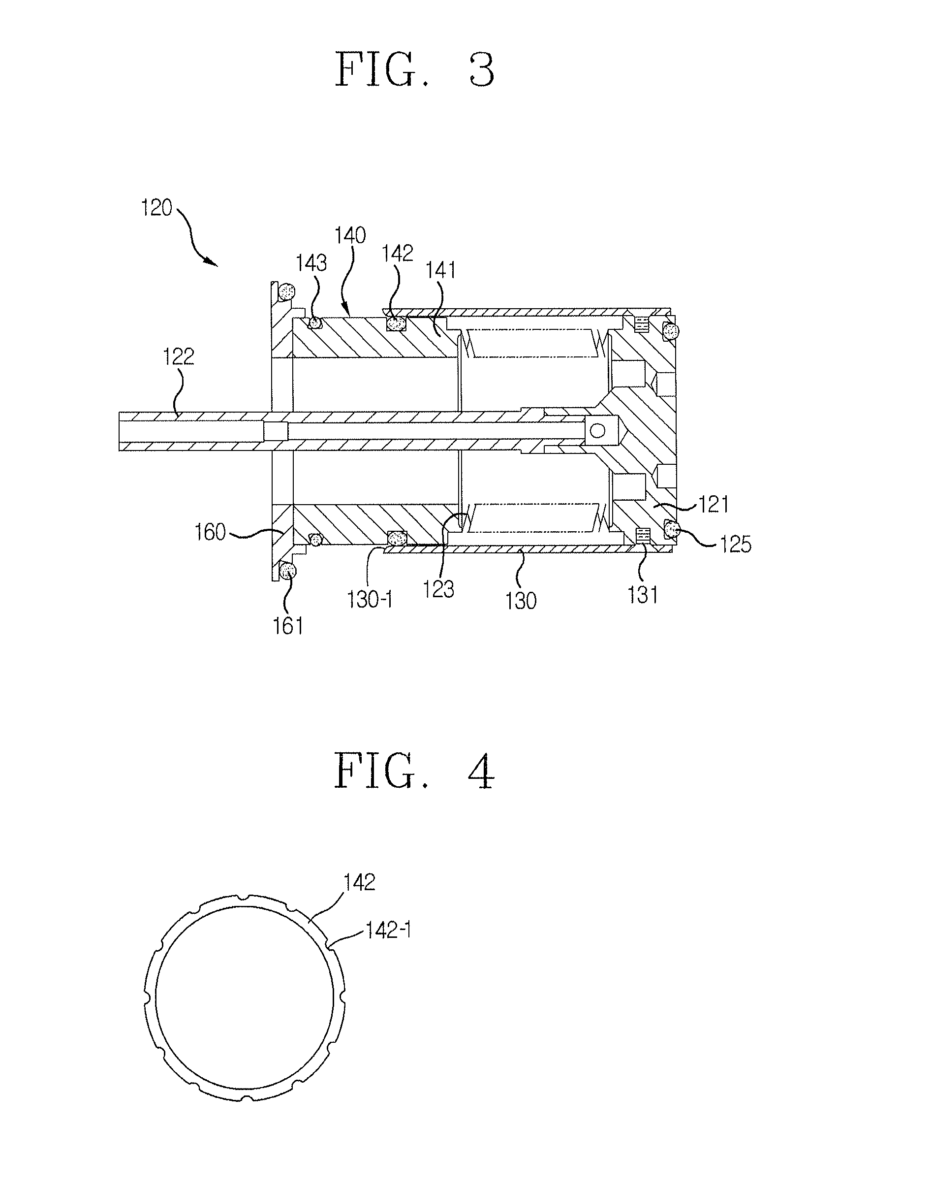
Provided is a valve for vacuum process, including: a first valve body having an inlet port and an outlet port; a sealing unit configured to move forward to and backward from the inlet port so as to have a closed position and an open position; a shaft covered with a bellows, and configured to move the sealing unit between the closed position and the open position; a cover for shielding the bellows from corrosive gas when the sealing unit is in the open position; and a cover guide unit configured to guide the cover to move along the shaft.

Description

RELATED APPLICATIONS[0001]Pursuant to 35 U.S.C. §119(a), this application claims the benefit of earlier filing date and right of priority to Korean Patent Application No. 10-2010-0115483, filed on Nov. 19, 2010, the contents of which are hereby incorporated by reference herein in their entirety.BACKGROUND[0002]1. Field[0003]The following description relates to a valve for vacuum process that controls the degree of a vacuum according to stages in a semiconductor manufacturing process.[0004]2. Description of the Related Art[0005]Vacuum systems are used for manufacturing semiconductor devices. In chemical vapor deposition (CVD) systems, when energy is provided to gas in a chamber to get a plasma state, a reaction occurs in a wafer in the chamber and a thin film is formed on the wafer. Unnecessary reactants generated in the process are discharged through pumps and pipes.[0006]These vacuum systems include valves for controlling the degree of the vacuum of pumps and pipes. Accordingly, fo...

Claims


Application Information

Patent Timeline
Patent Type & Authority Patents(United States)
IPC IPC(8): F16K31/126F16K31/122F16J3/06
CPCF16K41/10F16K31/122H01L21/67017F16K51/02
Inventor LEE, DONG-MIN
Owner LEE DONG MIN
Learn More