Method and Apparatus for maintaining airway patency and pressure support ventilation

a pressure support ventilation and airway patency technology, applied in the field of airflow generation means, can solve the problems of high cost of standard bi-level products, and many patients' inability to tolerate continuous positive airway pressure, etc., and achieve the effect of lessening unnatural sensation and discomfor

Inactive Publication Date: 2016-10-27
ARNOTT RICHARD J
View PDF4 Cites 2 Cited by
  • Summary
  • Abstract
  • Description
  • Claims
  • Application Information

AI Technical Summary

Benefits of technology

[0012]It is further the objective of the invention to lessen the unnatural sensation and discomfort experienced by the patient in overcoming the traditional positive pressure during breath exhalation.
[0013]It is further the objective of the invention to supply the device as a simple add-on product to convert these traditional CPAP units to a useful source of treatment without considerable expense.

Problems solved by technology

Unfortunately there are several circumstances where a continuous positive pressure air or gas source is not comfortable, reasonable or useful and a standard bi-level product is cost prohibitive.
Many patients cannot tolerate the application of continuous positive airway pressure, particularly because of the discomfort associated with exhalation against a continuous positive pressure or the dryness that accompanies this type of delivery.
Although more expensive devices may be available that provide relief upon exhalation, they are cost-prohibitive, designed for a single use and tightly regulated by insurance companies.
In some cases no device is available at all.
In addition, when different drugs, including oxygen, are delivered to a patient via continuous pressure the drug amount is difficult to regulate because breathing rates differ from patient to patient.
Coordinating inhalation of drug delivery with the breathing cycle is impossible.
However, there is no method or device that can be added to an existing continuous positive air or gas source which will convert them for the application and delivery of bi-level positive airway pressure to a patient.
The systems, methods and apparatus disclosed in the prior art for treating patients afflicted with such maladies as sleep apnea, snoring, ventilation support and pharmaceutical delivery present a number of problems which need to be addressed.
The equipment utilized in such treatment is far too limiting.
An alternative, much more expensive device is rejected by many insurance companies.

Method used


Image

  • Method and Apparatus for maintaining airway patency and pressure support ventilation
  • Method and Apparatus for maintaining airway patency and pressure support ventilation
  • Method and Apparatus for maintaining airway patency and pressure support ventilation

Examples


Embodiment Construction

[0037]The invention will now be described in detail in relation to a preferred embodiment and implementation thereof which is exemplary in nature and descriptively specific as disclosed. As is customary, it will be understood that no limitation of the scope of the invention is thereby intended. The invention encompasses such alterations and further modifications and applications as would normally occur to persons skilled in the art to which the invention relates. This detailed description of this invention is not meant to limit the invention, but is meant to provide a detailed disclosure of the best mode of practicing the invention.

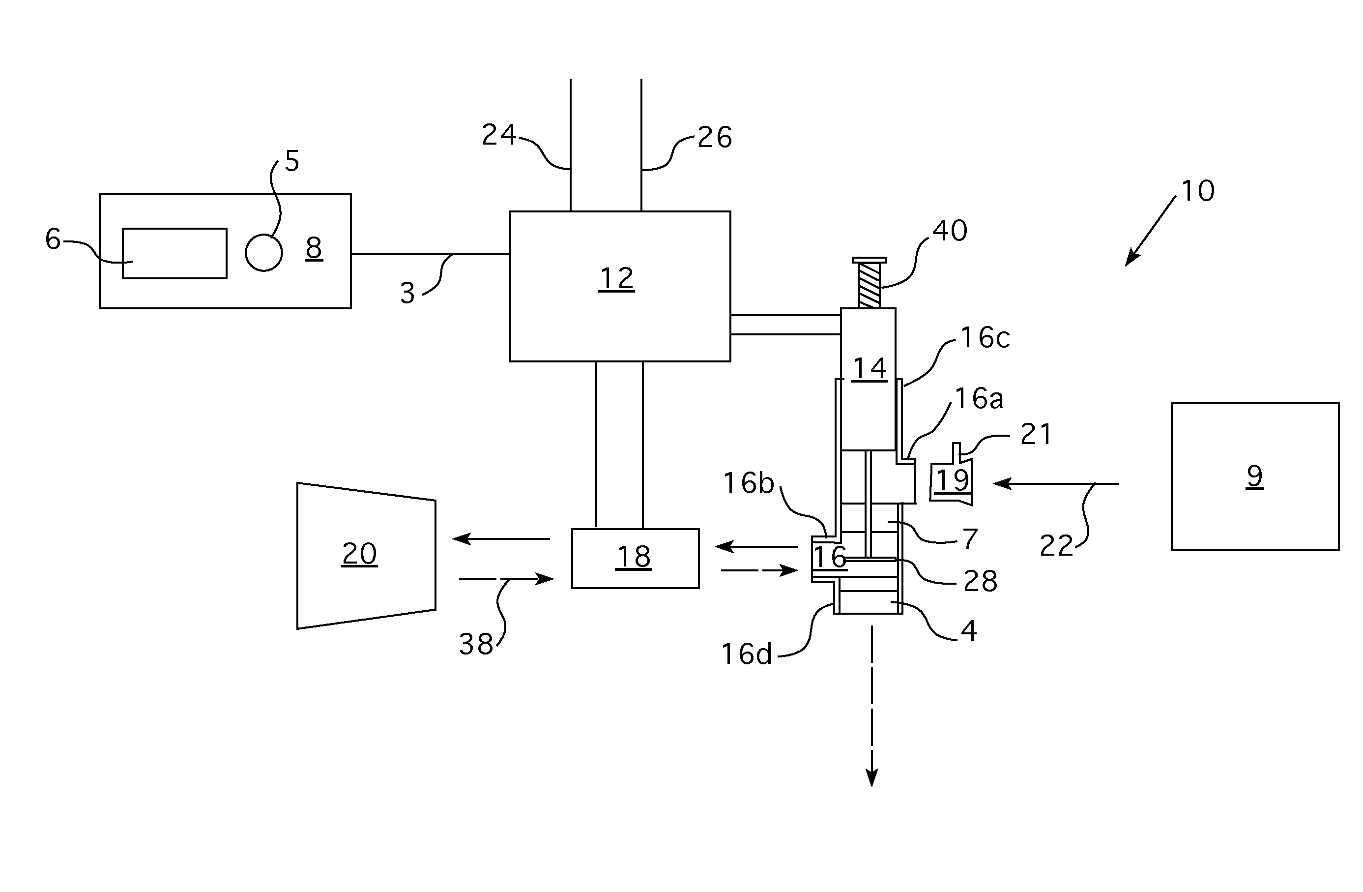
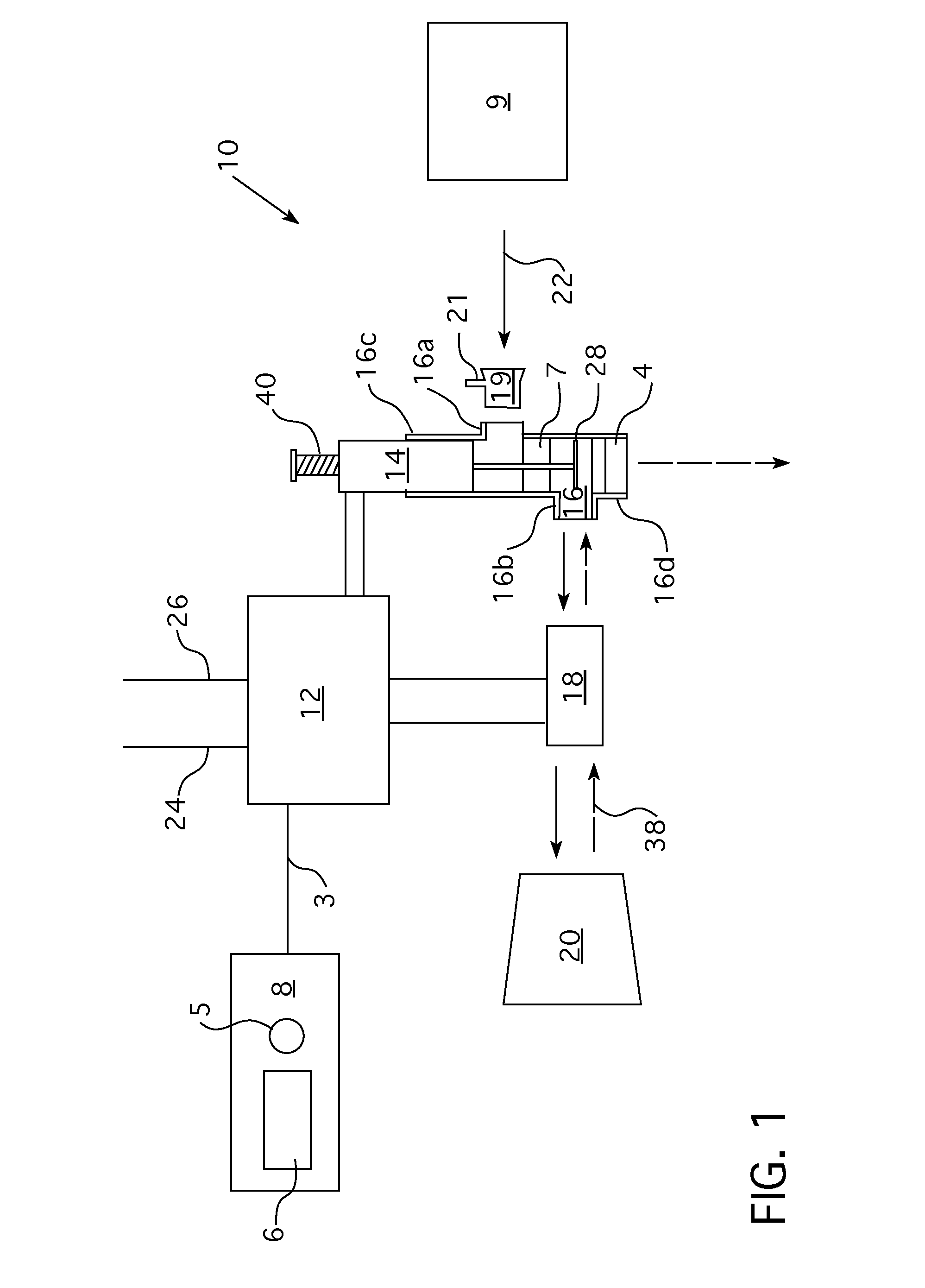
[0038]With reference then to FIGS. 1-6, illustrated is an assembly 10 which includes valve assembly 16, a programmable controller circuit 12 encoded by programmer 8, a normally-open electrical switch / sensor 18, and a patient interface device 20 such as a mask, tracheal tube, nasal cannula or similar patient interface, and an optional drug delivery port 19...


PUM


Abstract

An assembly for modifying airflow into a nasopharyngeal airway or trachea of a patient. A valve assembly is adapted to attach to an airflow generator. A linear actuator is signaled by the airflow. An inhalation valve is within the feed tube at the inlet. An exhalation valve is within the feed tube at the outlet, the exhalation valve adapted to slide axially within the feed tube and incrementally cover the outlet, moving in unison with the inhalation valve. A drive means operates the inhalation valve and the exhalation valve simultaneously such that upon sliding of the inhalation valve toward the mask side, the exhalation valve thereby slides towards the mask side, wherein upon activation of both the airflow generator and a controller circuit, pressurized air from the airflow generator continuously enters the feed tube but is converted to a single, repeatable burst.

Description

CROSS-REFERENCE TO RELATED APPLICATIONS[0001]The instant application is a continuation-in-part of U.S. application Ser. No. 14 / 460,385, filed Aug. 15, 2014, which was a continuation-in-part of U.S. application Ser. No. 14 / 011,845, filed Aug. 28, 2013, now abandoned, which was a continuation-in-part of U.S. application Ser. No. 12 / 897,809, filed Oct. 5, 2010, now U.S. Pat. No. 8,544,468, which claimed benefit of provisional application Ser. No. 61 / 249,323 filed Oct. 7, 2009 and provisional application Ser. No. 61 / 258,257 filed Nov. 5, 2009, the disclosures of all of which are incorporated herein by reference.BACKGROUND[0002]1. Field of the Invention[0003]The invention relates to the modification of pre-existing airflow generation means to produce a pressurized airflow burst or flow of air directed into the nasopharyngeal airway or trachea of the patient as a patient's inhalation action continues or is caused to occur.[0004]2. Description of the Related Art[0005]Breathing disorders or...

Claims


Application Information

Patent Timeline
Patent Type & Authority Applications(United States)
IPC IPC(8): A61M16/20A61M16/04A61M16/08A61M16/00A61M16/06
CPCA61M16/204A61M16/0066A61M16/0666A61M16/0875A61M2202/0208A61M16/0816A61M16/04A61M2205/50A61M16/205A61M2205/42A61M15/00A61M16/20A61M2016/0024A61M2205/0266A61M16/202A61M16/022
Inventor ARNOTT, RICHARD J.
Owner ARNOTT RICHARD J
Why Eureka
Try Eureka