Stability controlled high frequency chopper-based oscillator

a high-frequency, chopper-based technology, applied in the direction of pulse automatic control, pulse generation by logic circuits, pulse techniques, etc., can solve the problems of significant temperature dependence and high mismatch between components

Active Publication Date: 2016-11-03
TEXAS INSTR INC
View PDF3 Cites 6 Cited by
  • Summary
  • Abstract
  • Description
  • Claims
  • Application Information

AI Technical Summary

Problems solved by technology

Another issue arising with oscillators is that there are components that have high mismatch with significant dependence on temperature, apart from the variations in values of resistance and capacitance affecting the frequency accuracy.

Method used


Image

  • Stability controlled high frequency chopper-based oscillator
  • Stability controlled high frequency chopper-based oscillator
  • Stability controlled high frequency chopper-based oscillator

Examples


Embodiment Construction

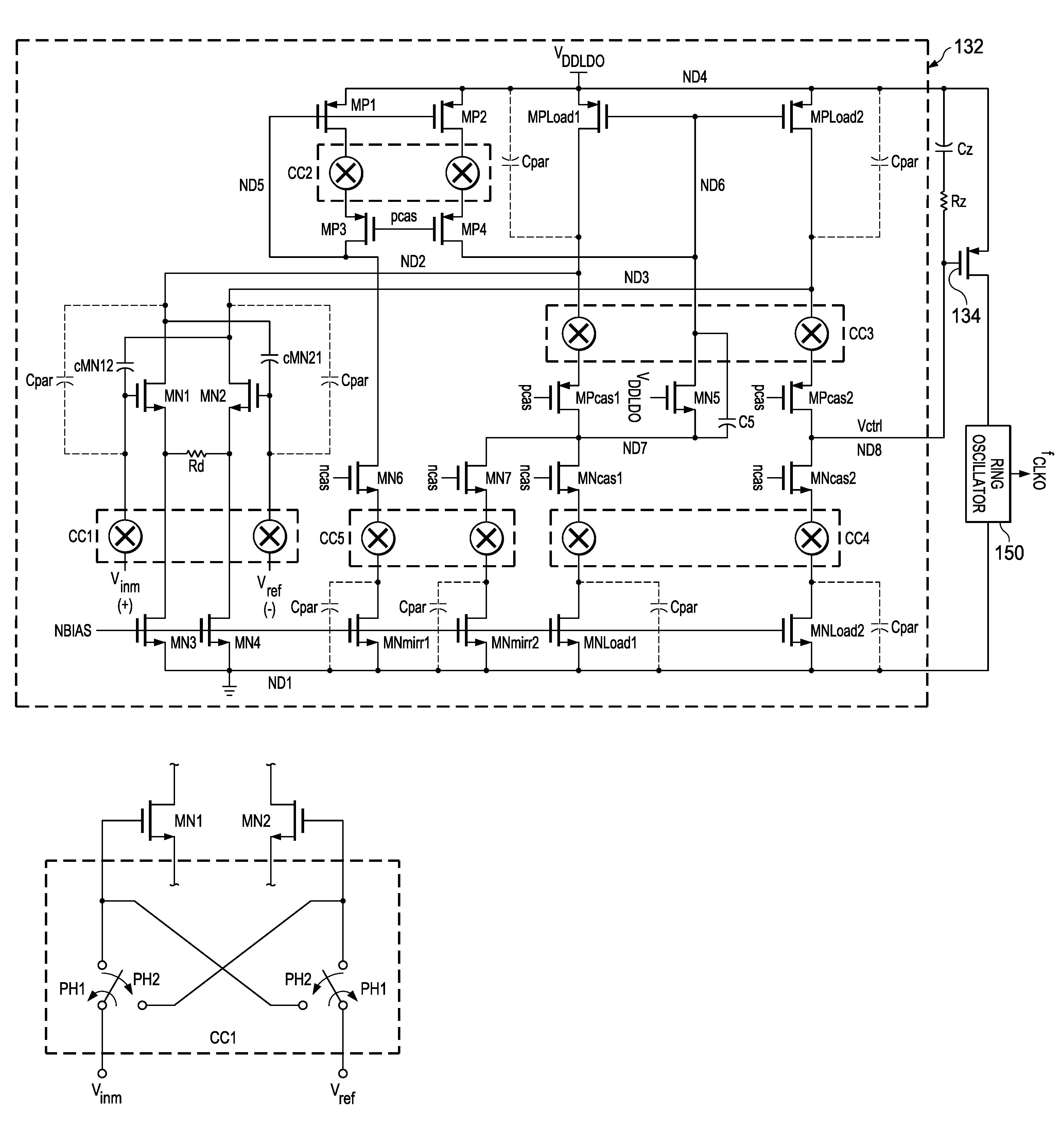
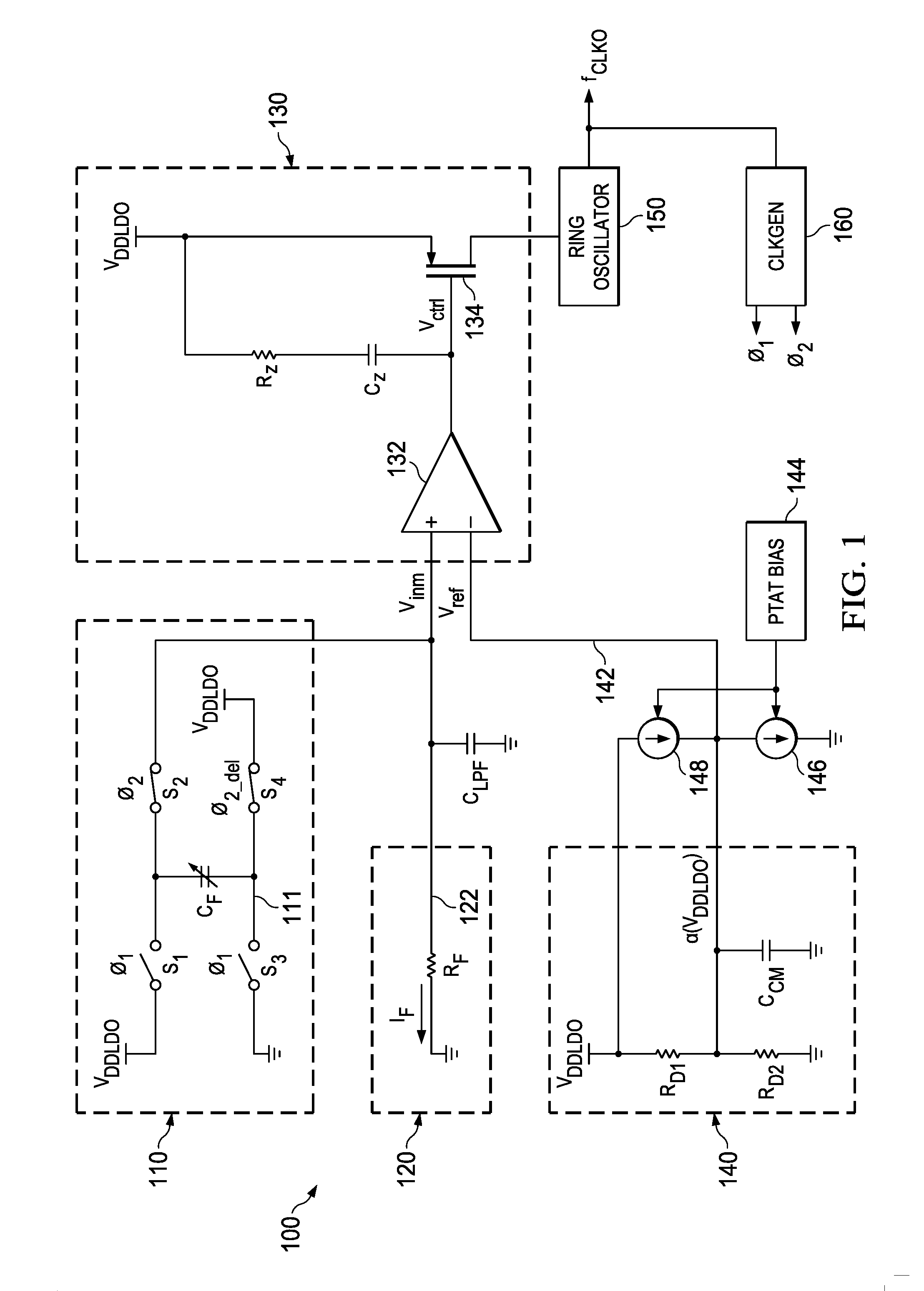
[0016]FIG. 1 illustrates a combined schematic and block diagram of an oscillator 100 according to a preferred embodiment, where some shared aspects of oscillator 100 are also described in co-owned U.S. patent application Ser. No. 14 / 587,951, filed Dec. 31, 2014, as further improved by various aspects described in this document. Oscillator 100 includes a feedback frequency-controlled current source 110 and a resistance based current source 120, both sharing a node 122 that connects a frequency-controlled voltage Vinm to a first input (e.g., non-inverting) of a transconductance circuit 130. Oscillator 100 also includes a voltage divider circuit 140, having a node 142 that connects a voltage Vref to a second input (e.g., inverting) of transconductance circuit 130. Transconductance circuit 130 has an output connected as an input to a ring oscillator 150, which may include a differential-to-single D2S circuit to convert signals to a rail-to-rail signal. The output of ring oscillator 150 ...


PUM


Abstract

Circuitry for providing an oscillating output signal. This circuitry includes a transconductance circuit having a first input, a second input, an output. The transconductance also includes a first transistor, a second transistor, and chopping circuitry. The chopping circuitry is for alternatively connecting, in a first clock cycle phase, a first node to a first terminal of the first transistor and a second node to a first terminal of the second transistor and, in a second clock cycle phase, following the first clock cycle phase, the first node to the first terminal of the second transistor and the second node to a first terminal of the first transistor. An oscillator circuit is also included and coupled to receive voltage from the output of the transconductance circuit, wherein the oscillating output signal is responsive to an output of the oscillator circuit. Further connected to the transconductance circuit are circuitry for providing a first voltage to its first input and a frequency controlled circuit for providing a second voltage to its second input.

Description

CROSS-REFERENCES TO RELATED APPLICATIONS[0001]This application claims priority to, the benefit of the filing date of, and hereby incorporates herein by reference, India Provisional Patent Application 2190 / CHE / 2015, entitled “METHOD TO TACKLE OVERLOADING ISSUES IN HIGH FREQUENCY CHOPPER-BASED OSCILLATORS” and filed Apr. 29, 2015.STATEMENT REGARDING FEDERALLY SPONSORED RESEARCH OR DEVELOPMENT[0002]Not Applicable.BACKGROUND OF THE INVENTION[0003]The preferred embodiments relate to electronic oscillators.[0004]Electronic oscillators are well-known devices operable to produce an oscillating output signal. Thus, electronic oscillators are well-known for timing and synchronization and occur in numerous electronic circuits, devices, and industries. In many of these applications, various or all of the oscillator components are combined into an integrated circuit. As such, design considerations contemplate the oscillator as well as the overall integrated circuit. For example, with respect to ...

Claims


Application Information

Patent Timeline
Patent Type & Authority Applications(United States)
IPC IPC(8): H03L7/24
CPCH03L7/24H03K3/0315H03L7/00H03K3/02H03K3/08H03K3/027H03K3/011
Inventor RAMANAN, RAMAMURTHY VENKATAMAHADEVAN, VENKITESWARAN
Owner TEXAS INSTR INC
Why Eureka
Try Eureka