Display device and head mounted display device

Active Publication Date: 2017-03-02
JAPAN DISPLAY INC
View PDF3 Cites 6 Cited by
  • Summary
  • Abstract
  • Description
  • Claims
  • Application Information

AI Technical Summary

Benefits of technology

The present invention aims to provide a display device that can provide a high-definition image while reducing the processing load for moving images. Specifically, it is designed to address challenges associated with the increasing processing demands introduced when higher definition in head mounted display devices is coupled with improved performance for moving images and three-dimensional displays. Ultimately, the invention offers a solution for providing high-definition imaging while reducing the processing load on the display device.

Problems solved by technology

However, when the higher definition in the head mounted display devices is further proceeded and performance for moving images and performance for three-dimensional displays are improved, a processing load imposed on the display device increases excessively.

Method used


Image

  • Display device and head mounted display device
  • Display device and head mounted display device
  • Display device and head mounted display device

Examples


first embodiment

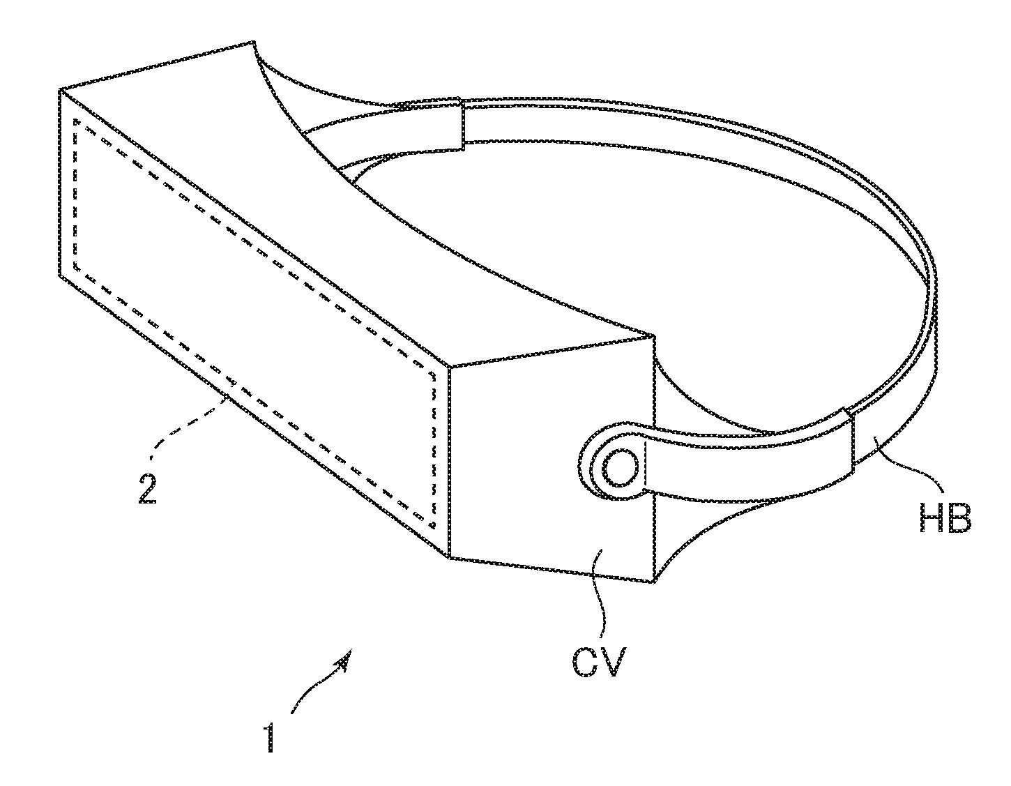
[0029]FIG. 1 is a perspective view for explaining a head mounted display 1 (a head mounted display device) according to a first embodiment. As shown in the figure, the head mounted display 1 according to the present embodiment includes an annular headband HB that can be locked to the head of a user, a cover member CV supported by the headband HB to cover the front of the eyes of the user, and a display device 2 detachably fixed (or integrally fixed) in front of the eyes of the user on the inside of the cover member CV.

[0030]The head mounted display 1 includes a not-shown receiving section to which an image signal and a sound signal are input. An image is displayed on the display device 2 on the basis of the image signal input to the receiving section. Sound is output from a not-shown speaker or the like on the basis of the sound signal input to the receiving section.

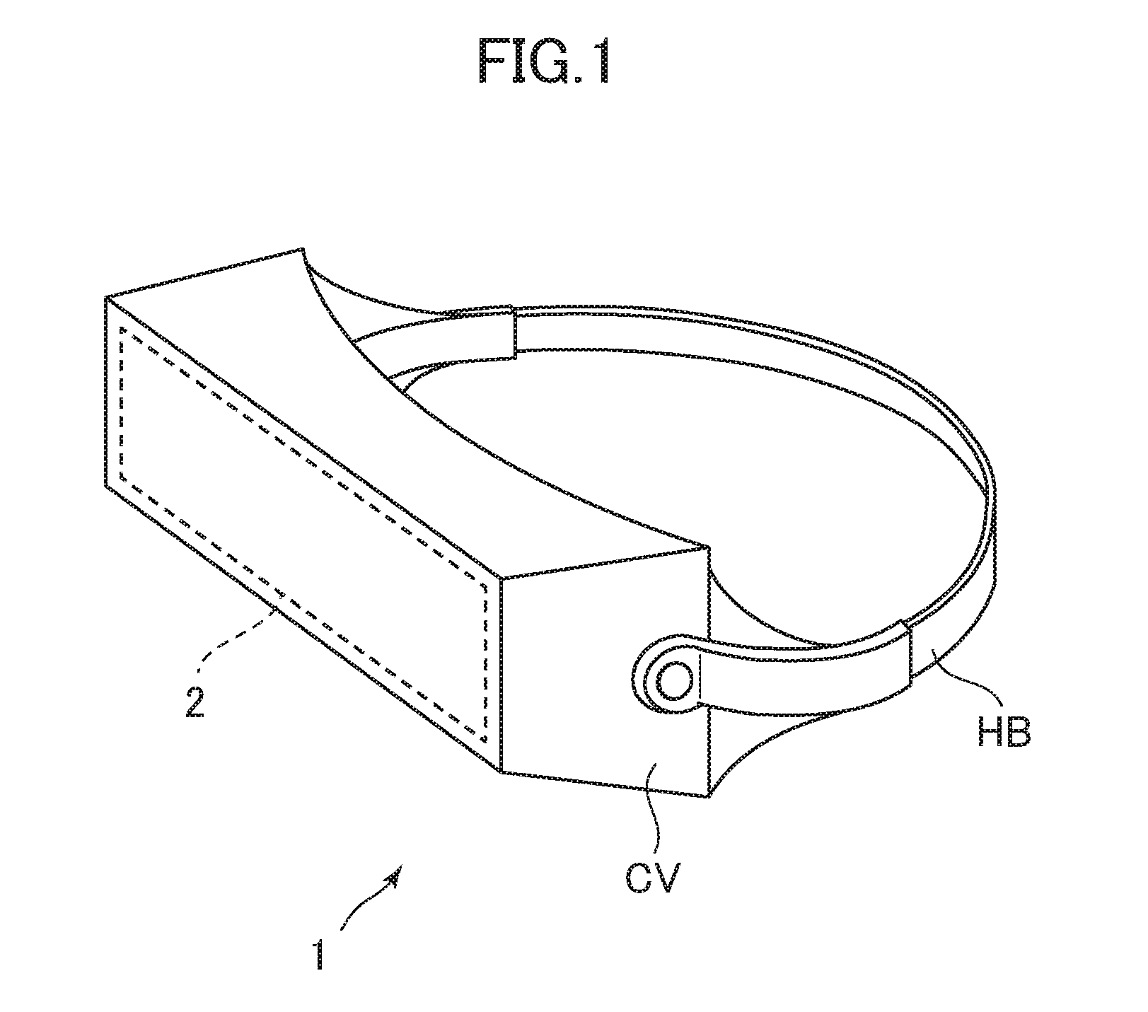
[0031]FIG. 2 is a schematic perspective view for explaining the display device 2 installed on the inside of the cover ...

second embodiment

[0052]The head mounted display 1 according to a second embodiment of the present invention will be explained.

[0053]FIG. 8 is a perspective view of the head mounted display 1 according to the second embodiment. FIG. 9 is a diagram for explaining a layout of pixels of the display device 2 according to the second embodiment.

[0054]As shown in FIG. 8, the head mounted display 1 according to the second embodiment includes two display devices 2 corresponding to the two eyes of a human on the inside of the cover member CV. The display device 2 disposed in front of the left eye of the display devices 2 has a layout of pixels shown on the left side in FIG. 9. The display device 2 disposed in front of the right eye has a layout of pixels shown on the right side in FIG. 9.

[0055]In the two display devices 2, as in the case of the first embodiment, the high-definition display sections HR having an area of a unit pixel smaller than the area of the other sections (that is, low-definition display se...

third embodiment

[0057]A head mounted display 1 according to a third embodiment of the present invention will be explained.

[0058]FIG. 10 is a diagram for explaining a cross section of a pixel of the high-definition display section HR near the boundary between the high-definition display section HR and the low-definition display section LR of the display device 2 according to the third embodiment. In the display device 2 according to the third embodiment, a drawn wiring layer L2 is further interposed between the first transparent conductive film T1 and the pixel electrode P1. Consequently, the display device 2 can also be adapted to a pixel layout having a larger distance between the thin-film transistor TFT2 and the pixel electrode P1. In other words, even in a circuit design in which regions surrounded by the video signal lines DL and the scanning signal lines GL has areas equal to each other, it is possible to achieve higher definition by reduce the size of the pixel electrode P1 of the high-defin...


PUM


Abstract

A display device includes a low-definition display section and a high-definition display section. An area of pixels of the high-definition display section is smaller than an area of pixels of the low-definition display section. The position of the center of the high-definition display section is shifted from the position of the center of the display region. Consequently, when the display device is worn on the head of a user and disposed in front of the eyes, it is possible to provide a high-definition image. It is possible to reduce a processing load of moving image processing.

Description

CROSS-REFERENCE TO RELATED APPLICATION[0001]The present application claims priority from Japanese application JP2015-165429 filed on Aug. 25, 2015, the content of which is hereby incorporated by reference into this application.BACKGROUND OF THE INVENTION[0002]1. Field of the Invention[0003]The present invention relates to a display device and a head mounted display device.[0004]2. Description of the Related Art[0005]There is known a head mounted display device (referred to as HMD as well) configured to provide an image on a display disposed in front of the eyes.[0006]JP 2013-117553 discloses an image display device that enables users to observe a realistic image displayed on a screen by increasing the screen in size and reduces manufacturing cost of the image display device and an amount of image data used during driving of the image display device.SUMMARY OF THE INVENTION[0007]Since head mounted display devices provide users with a large angular field of view despite its screen siz...

Claims


Application Information

Patent Timeline
IPC IPC(8): G06T3/40G06T7/40H01L27/32G06T7/00
CPCG06T3/40G06T7/004G06T7/408G06T2207/20112H01L27/322G06T2210/36G06T7/0081G02B2027/0147G02B27/0172H10K59/352H10K59/38
Inventor NAKAMURA, TOMOKIHANARI, JUN
Owner JAPAN DISPLAY INC
Why Eureka
Try Eureka