

Bolometer with high spectral sensitivity
a bolometer and high spectral sensitivity technology, applied in the field of bolometers, can solve the problems of increasing thermal mass, thermal time constant, and not offering high spectral selectivity
Inactive Publication Date: 2017-04-13
COMMISSARIAT A LENERGIE ATOMIQUE ET AUX ENERGIES ALTERNATIVES
View PDF5 Cites 8 Cited by
- Summary
- Abstract
- Description
- Claims
- Application Information
AI Technical Summary
Benefits of technology
The invention is a bolometric detector with a narrow absorption peak and low absorption areas around it, which results in high sensitivity and selectivity to a specific wavelength. This feature allows for the detection of small amounts of light without the need for a spectral filter. The detector can also have adjacent pixels that are sensitive to different wavelengths, without experiencing cross-talk. Overall, the invention allows for more accurate and efficient detection of light.
Problems solved by technology
A drawback of this bolometer is that it does not offer high spectral selectivity, all the wavelengths being absorbed over a spectral width of several micrometres.
A drawback of these stacks deposited on the absorbent membrane is that they increase the thermal mass of the latter, and thus the thermal time constant.
Method used
View moreImage
Smart ImageViewing Examples

Examples
first embodiment
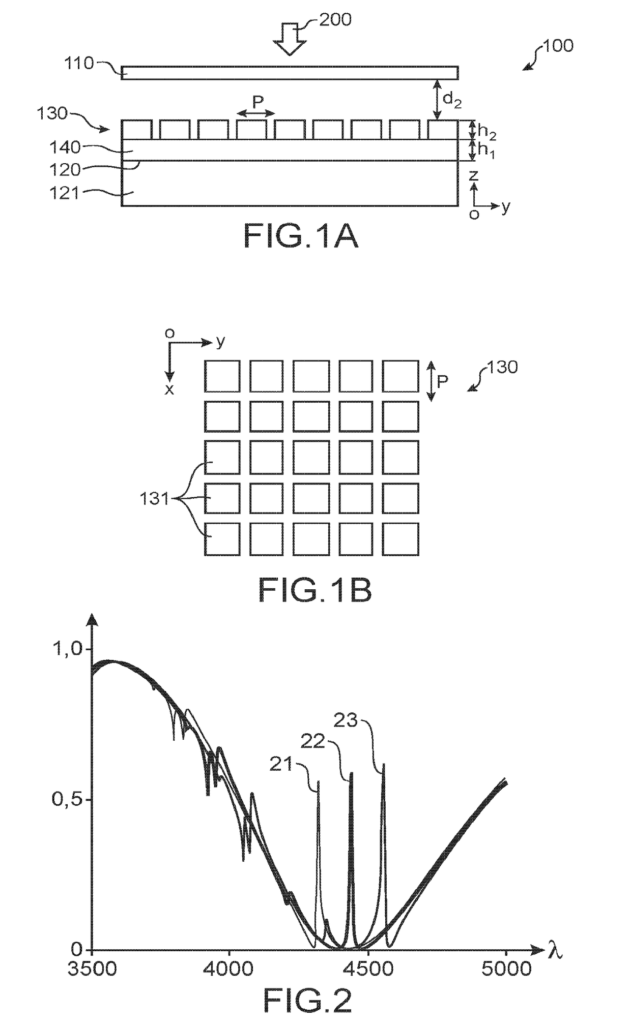
[0049]FIGS. 1A and 1B schematically illustrate, along two sectional views, a bolometric detector according to the invention;
[0050]FIG. 2 illustrates absorption spectra of bolometric detectors of the type of that of FIGS. 1A and 1B;
second embodiment
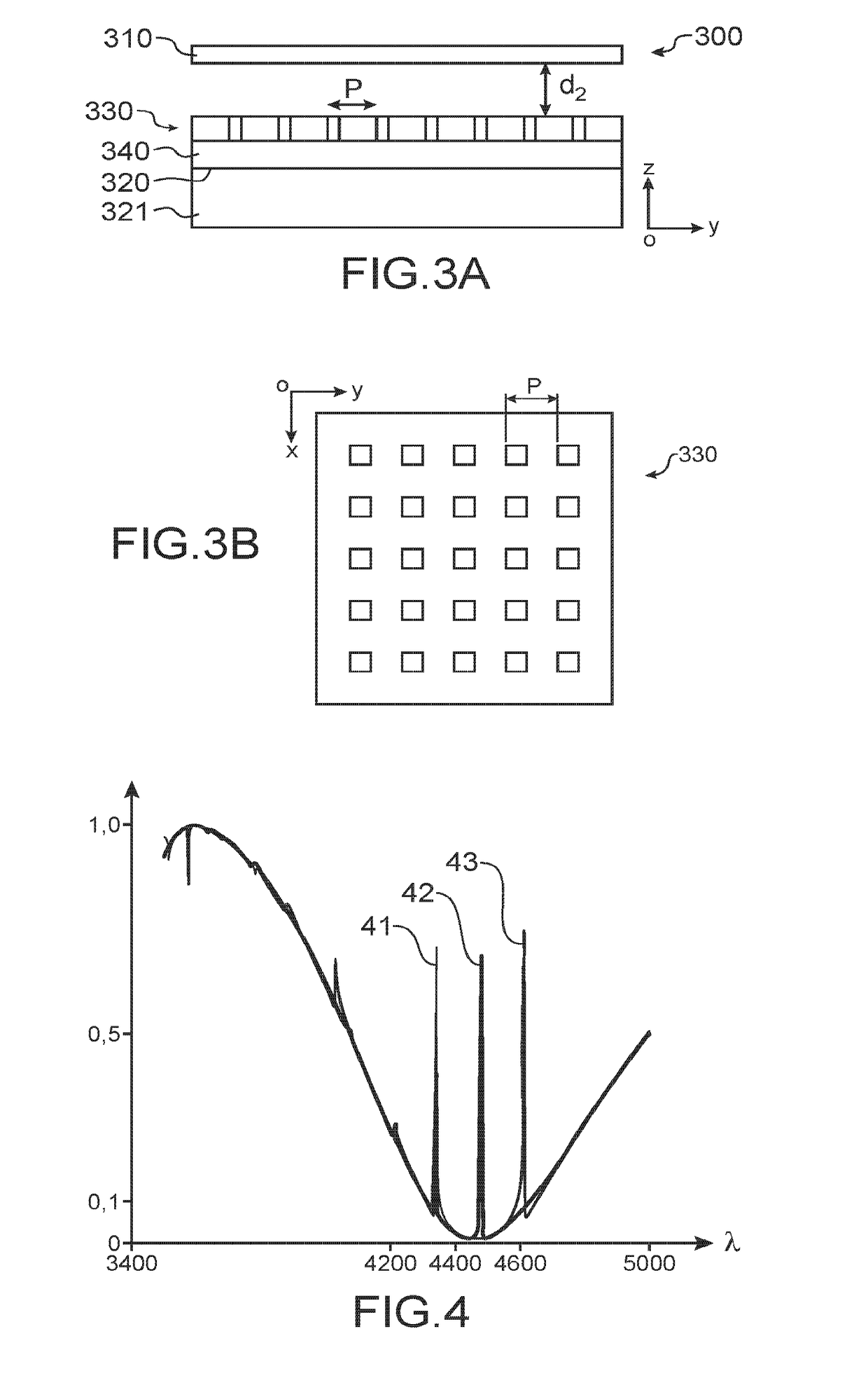
[0051]FIGS. 3A and 3B schematically illustrate, along two sectional view, a bolometric detector according to the invention;
[0052]FIG. 4 illustrates absorption spectra of bolometric detectors of the type of FIGS. 3A and 3B;
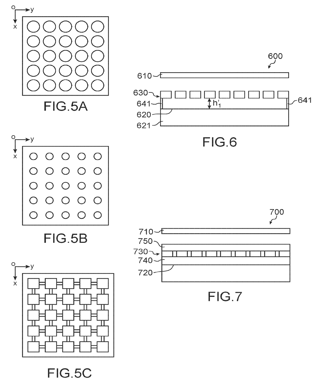
[0053]FIGS. 5A to 5C illustrate different variants of a structured layer of a bolometric detector according to the invention;
third embodiment
[0054]FIG. 6 schematically illustrates a bolometric detector according to the invention;
Login to View More PUM
 Abstract
A bolometric detector including an absorption membrane, for converting an incident electromagnetic radiation into heat; and a reflector, for reflecting to the absorption membrane part of the incident electromagnetic radiation having passed there through, is provided. The bolometric detector includes a non-metallic layer, situated between the absorption membrane and the reflector, having a series of index jumps, so as to form a network resonating at a wavelength of interest λ0; the mean pitch of the network is less than λ0; and the optical distance between the absorption membrane and the reflector is substantially equal to a multiple of λ0 / 2.
Description
TECHNICAL FIELD[0001]The invention relates to a bolometric detector, that is to say a detector that converts the energy of incident electromagnetic radiation into heat, such that an intensity of this radiation corresponds to a temperature variation.[0002]Bolometric detectors are notably suited to detecting electromagnetic radiation situated in the infrared, in particular at wavelengths comprised between 0.7 μm and 3 mm.STATE OF THE PRIOR ART[0003]Bolometers as described in FIG. 1A of patent application FR-2977937 are known from the prior art, comprising a membrane forming an absorber-thermistor unit, suspended above a reflector, at a distance λ0 / 4 therefrom, where λ0 is the central wavelength of a spectral detection band.[0004]The membrane comprises an absorbing element such as a thin layer of metal, which absorbs an incident electromagnetic radiation and of which the temperature increases in reaction to this absorption, and a thermometric element of which the resistivity varies wit...
Claims
Login to View More Application Information
Patent Timeline
 IPC IPC(8): G01N21/3504G01J5/34
CPCG01N21/3504G01J2005/106G01J5/34G01J5/0803G01J5/024G01J5/10G01J5/20
InventorBOUTAMI, SALIMELOI, FABIENHAZART, JEROMEYON, JEAN-JACQUES
OwnerCOMMISSARIAT A LENERGIE ATOMIQUE ET AUX ENERGIES ALTERNATIVES