

Bearing ring and layer by layer method for manufacturing a bearing ring
a technology of bearing rings and layers, applied in the direction of bearing cooling, machines/engines, mechanical equipment, etc., can solve the problems of greater power losses at the rolling contacts, higher thermal stresses on the bearing components, and increased surface pressure at the rolling contacts
Inactive Publication Date: 2017-09-28
SCHAEFFLER TECH AG & CO KG
View PDF3 Cites 1 Cited by
- Summary
- Abstract
- Description
- Claims
- Application Information
AI Technical Summary
Benefits of technology
The present invention relates to a cooling system for a bearing that improves heat transfer and strength while also being more compact. The cooling channels are designed to match the shape of the raceway being cooled, which reduces power loss and thermal stress on the bearing components. Additionally, the introduction of the cooling channels and the optimized cross-sectional shape allows for greater heat flow transport while using less cooling liquid.
Problems solved by technology
A more compact construction is likewise possible: in principle, a more compact construction, under the same external load, results in greater surface pressures at the rolling contacts.
Associated therewith are greater power losses at the rolling contacts and, therefore, higher thermal stresses on the bearing components.
Method used
View moreImage
Smart ImageViewing Examples

Examples
Embodiment Construction
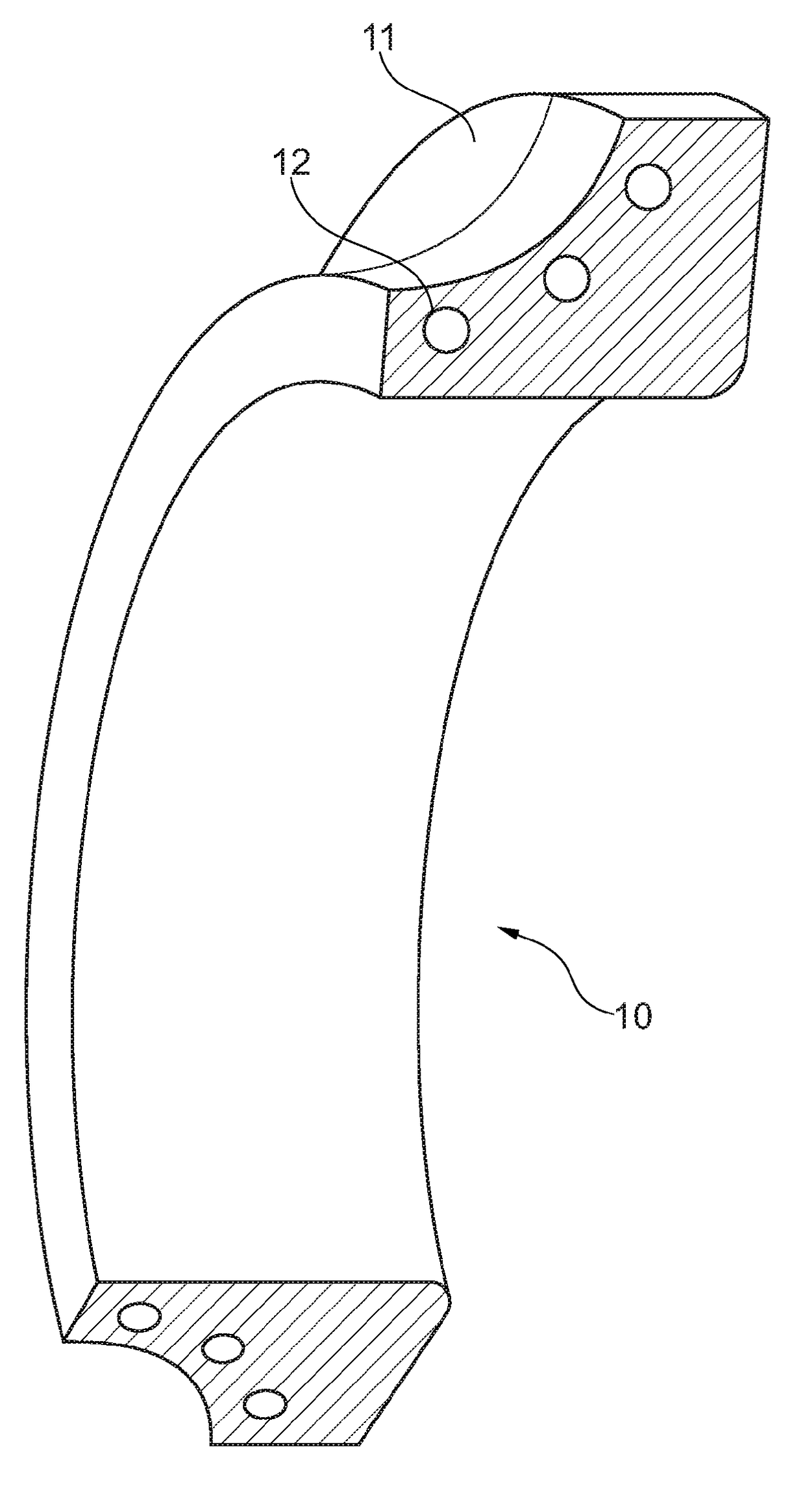
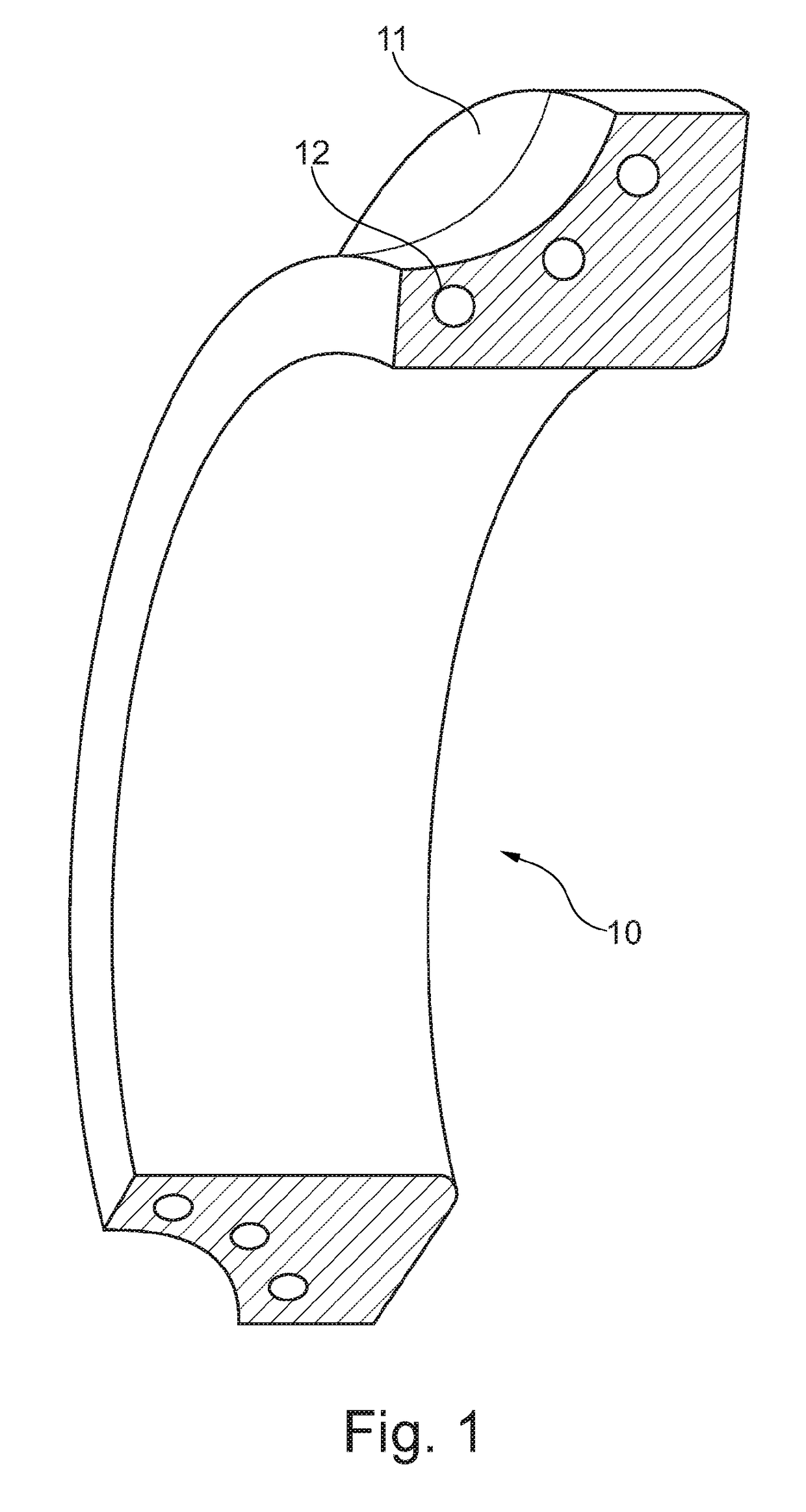
[0017]FIG. 1 shows a cross section of a bearing ring 10 according to the present invention, including channels 12 introduced along raceway 11.
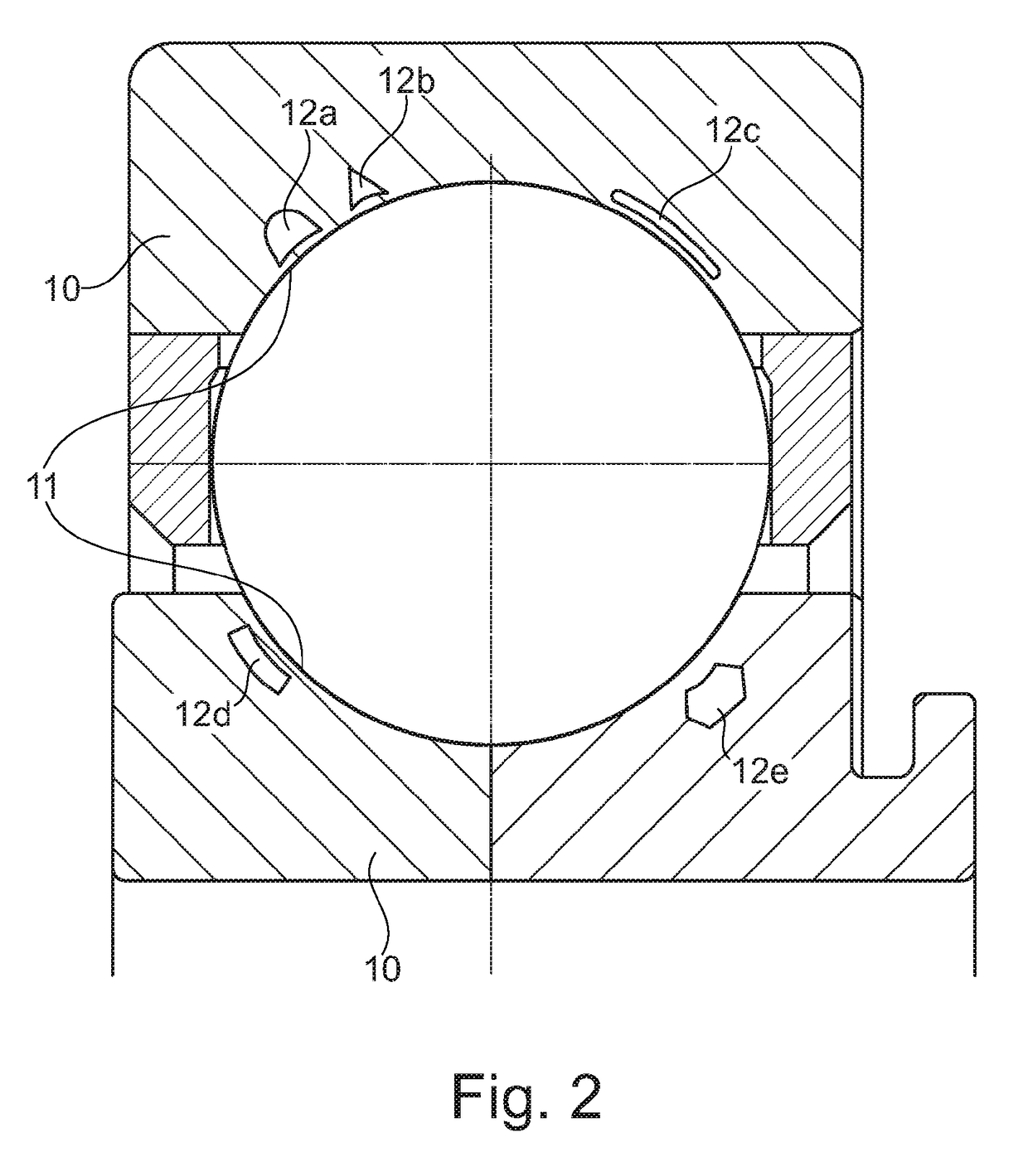
[0018]FIG. 2 shows a cross section of a bearing including bearing rings 10 according to the present invention. Various channels 12a, 12b, 12c, 12d, 12e having various cross-sectional shapes are apparent along the raceways 11.
Login to View More PUM
| Property | Measurement | Unit |
|---|---|---|
| Shape | aaaaa | aaaaa |
Abstract
A bearing ring with integrated cooling channels and a method for producing a bearing ring with integrated cooling channels are provided.
Description
[0001]The present invention relates to a bearing ring including integrated cooling channels and to a method for manufacturing a bearing ring including integrated cooling channels.BACKGROUND[0002]Bearing rings in aircraft engines are generally exposed to high rollover loads and high operating temperatures. This applies in particular for bearing rings in bearing systems for main shafts. The materials used for such bearing rings are predominantly heat-resistant, fully hardened or case-hardened steels, such as, for example, M50 (AMS 6491), M50NiL (AMS 6278), RBD, Pyrowear 675 (AMS 5930).[0003]The heat dissipation from the contact areas takes place with the aid of a continuous oil flow. In this case, an improved heat dissipation from the contact area may effectuate an increase in the performance of bearings, for example, in the engine area. A heat dissipation approach is known, for example, from EP 2 503 107 B1 which describes a bearing system for a turbomachine, one bearing housing part...
Claims
Login to View More Application Information
Patent Timeline
 IPC IPC(8): F01D25/12F16C37/00F16C33/64F16C33/58F01D25/18F16C33/62
CPCF01D25/125F01D25/186F16C33/62F16C33/6659F16C33/581F16C37/007F16C2220/00F16C33/64F16C19/06F16C33/60F16C33/583B22F3/24B22F5/10C22C33/0271B22F2999/00F16C2360/23F16C2204/62Y02P10/25Y02T50/60B22F10/28B22F2003/241B22F2201/30B22F2207/01
InventorBEER, OSKARGLOECKNER, PETER
OwnerSCHAEFFLER TECH AG & CO KG