Turbomachine arrangement

a technology of turbomachine and expansion tube, which is applied in the direction of compression machines using turbines, engine fuction, lighting and heating apparatus, etc., can solve the problems of reducing energy recovery potential, unable to always operate the compressor or expander in the optimal speed range, and applying additional energy, etc., to simplify the structural layout and the set-up and maintenance of the turbomachine arrangemen

Active Publication Date: 2017-10-26
ATLAS COPCO ENERGAS
View PDF5 Cites 0 Cited by
  • Summary
  • Abstract
  • Description
  • Claims
  • Application Information

AI Technical Summary

Benefits of technology

[0012]The transmission advantageously comprises a gear which meshes with a pinion disposed on the drive shaft. The gear advantageously has a larger diameter than the pinion and thereby establishes a speed change of its drive to the speed of the drive shaft. The gear is preferably solid and can therefore also function as a flywheel for stabilizing the speed of the compressor driven by the transmission.
[0013]In an embodiment, the rotational axis of the shaft, the rotational axis of the drive shaft and the rotational axis of the gear lie in one plane. This simplifies the structural layout and the set-up and maintenance of the turbomachine arrangement.

Problems solved by technology

Since the quantity of energy recovered from the expander is usually not sufficient for operating the compressor, it is necessary to apply additional energy.
This has the disadvantage, however, that neither the compressor nor the expander can always be operated in the optimal speed range.
Thus, the energy recovery potential is reduced due to additional conversion losses.
In addition, the fact that there are two separate systems results in a need for a greater amount of maintenance and space.

Method used


Image

  • Turbomachine arrangement
  • Turbomachine arrangement

Examples


Embodiment Construction

[0018]The following is a detailed description of example embodiments of the invention depicted in the accompanying drawings. The example embodiments are presented in such detail as to clearly communicate the invention and are designed to make such embodiments obvious to a person of ordinary skill in the art. However, the amount of detail offered is not intended to limit the anticipated variations of embodiments; on the contrary, the intention is to cover all modifications, equivalents, and alternatives falling within the spirit and scope of the present invention, as defined by the appended claims.

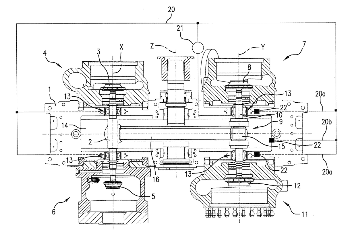
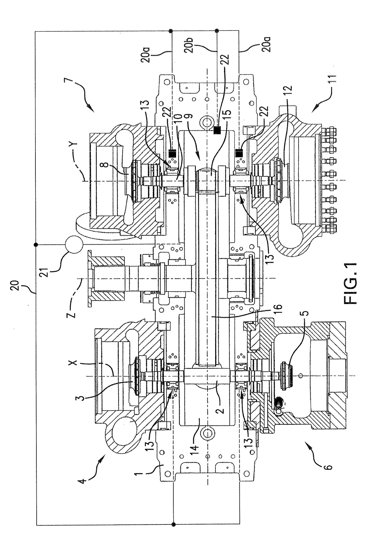
[0019]The FIG. 1 turbomachine arrangement comprises a housing 1 and a shaft 2, which is rotatably mounted on the housing 1. The shaft 2 connects an expander rotor 3 of a turbo-expander 4 to a first compressor rotor 5 of a first turbo-compressor 6. An additional drive is not disposed on the shaft 2, and therefore the first compressor rotor 5 can be driven exclusively by the expander rotor 3....


PUM


Abstract

A turbomachine arrangement includes a housing, a turbo-expander formed with an expander rotor, a turbo-compressor formed with a first compressor rotor, and a shaft that is rotatably mounted on the housing. The shaft connects the expander rotor to the compressor rotor. The first turbo-compressor can be driven exclusively by the turbo-expander. A second turbo-compressor having a second compressor rotor is disposed on the housing such that the second compressor rotor is connected to the first turbo-compressor in parallel or in series. The second compressor rotor is driven via a transmission accommodated in the housing and via a drive shaft connecting the transmission to the second compressor rotor.

Description

CROSS-REFERENCE TO A RELATED APPLICATION[0001]The invention described and claimed hereinbelow also is described in German Patent Application 10 2016 107 341.5, filed on Apr. 20, 2016. The subject matter of the German Patent Application is incorporated herein by reference and, provides the basis for a claim of priority of invention under 35 U.S.C. 119(a)-(d).BACKGROUND OF THE INVENTION[0002]The present invention relates to a turbomachine arrangement, including a housing, a turbo-expander comprising an expander rotor, a turbo-compressor comprising a first compressor rotor, and a shaft, which is rotatably mounted on the housing. The shaft connects the expander rotor to the first compressor rotor.[0003]Known turbomachine arrangements, sometimes referred to as “companders” (compressor-expanders), are used during the expansion of a fluid (in cooling circuits, for example) for recovering pressure energy in the expander and making this usable for the compressor which is coupled to the expan...

Claims


Application Information

Patent Timeline
Patent Type & Authority Applications(United States)
IPC IPC(8): F04D25/04F04D25/16F04D17/10F04D29/053F04D29/056F04D29/063F04D29/42F25B11/04
CPCF04D25/04F04D17/10F04D25/16F04D29/4206F04D29/056F04D29/063F25B11/04F04D29/053F01D15/005F02C6/02F02C6/12F02C7/36F05D2220/40F05D2240/40F05D2260/40F04D25/163
Inventor JANITSCHKE, KLAUS
Owner ATLAS COPCO ENERGAS
Why Eureka
Try Eureka