Wave energy converter with a differential cylinder

Active Publication Date: 2018-05-17
W4P WAVES4POWER AB
View PDF0 Cites 4 Cited by
  • Summary
  • Abstract
  • Description
  • Claims
  • Application Information

AI Technical Summary

Benefits of technology

[0006]A first object of the present invention is therefore to provide a wave energy converter having an acceleration tube and an improved energy conversion assembly which, as compared to the previously utilized assemblies, has a lower total weight and a better weight distribution an

Problems solved by technology

A disadvantage of the previously known wave energy converters with acceleration tubes and energy collecting devices in the form of hydraulic piston pumps is that the previously utilized pumps are usually designed as a cylinder with a through-going piston rod and require a large length of stroke to enable a sufficiently high pumping flow rate to be achieved, resulting in that the energy conversion assembly as a whole will require a large space.
This usually results in a large weight of the wave energy converter and in that components of the energy conversion

Method used


Image

  • Wave energy converter with a differential cylinder
  • Wave energy converter with a differential cylinder
  • Wave energy converter with a differential cylinder

Examples


Embodiment Construction

[0035]In the following, a number of embodiments of a wave energy converter according to the invention will be described in greater detail with reference to the accompanying FIGS. 1-3.

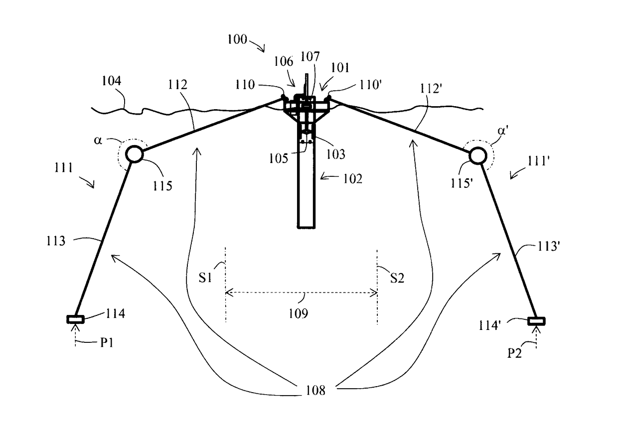
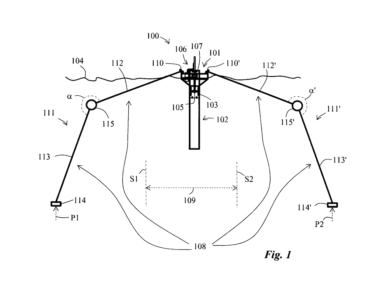
[0036]The wave energy converter 100 comprises a buoyant body 101, which can be of any type and design suitable for the purpose. An acceleration tube 102 is dependent from and attached to the buoyant body 101 and has an upper end adjacent to the buoyant body and a lower end at a distance from the buoyant body, wherein a portion of the acceleration tube 102 defines a working cylinder 103 between the upper end and the lower end. Wave energy converters with acceleration tubes are well known to a skilled person in the field, for example from the patent publications SE 508 307 and SE 508 308. Upper and lower openings in the acceleration tube 102 allow a substantially unimpeded flow of water between the working cylinder 103 and a body of water 104 in which the acceleration tube 102 is at least partially submer...


PUM


Abstract

A wave energy converter includes a buoyant body and an acceleration tube with a working cylinder and working piston movable therein, a mooring system, and at least one energy collecting device including a differential cylinder having an internal pump piston connected to the working piston via a piston rod. The differential cylinder includes a pumping chamber and an annular pumping chamber. When decreasing volume of the annular gap-shaped pumping chamber, the pump piston expels hydraulic fluid from the pumping chamber toward the pressure accumulator and draws hydraulic fluid from the fluid tank into the substantially cylindrical pumping chamber. During a working stroke causing a decrease in volume of the substantially cylindrical pumping chamber, the pump piston causes hydraulic fluid to bypass the pump piston through a fluid connection from the substantially cylindrical pumping chamber into the annular gap-shaped pumping chamber and further in a direction toward the pressure accumulator.

Description

TECHNICAL FIELD[0001]The present invention relates to a wave energy converter comprising a buoyant body, an acceleration tube dependent from and attached to the buoyant body and defining a working cylinder between an upper and a lower end thereof, upper and lower openings in the acceleration tube, a working piston reciprocable in the working cylinder, a mooring system adapted to maintain the wave energy converter within a desired anchoring area, and an energy conversion assembly comprising at least one energy collecting device collecting energy from the movements of the working piston relative to the buoyant body resulting from wave movements.BACKGROUND OF THE INVENTION[0002]Wave movements in oceans and large lakes constitute an important source of energy which can be utilized by harvesting energy from the waves by means of wave power assemblies, also called wave energy converters, which are positioned or anchored at locations with suitable wave conditions.[0003]A number of differen...

Claims


Application Information

Patent Timeline
IPC IPC(8): F03B13/18F04B53/14F04B9/10F04B53/12
CPCF03B13/1875F04B53/144F04B9/10F04B53/125F05B2260/406F04B17/00F04B35/00Y02E10/30F03B13/187F03C1/0076F04B35/004F04B39/0016
Inventor ALM, FILIP
Owner W4P WAVES4POWER AB
Why Eureka
Try Eureka