Submersible vessel having retractable wing and keel assemblies

a technology of keel and wing, which is applied in the field of wind-powered submersible vessels having wing and keel assemblies, can solve the problems of high cost, large size, and restricted mainly, and achieve the effect of reducing drag

Active Publication Date: 2018-06-14
OCEAN AERO
View PDF8 Cites 14 Cited by
  • Summary
  • Abstract
  • Description
  • Claims
  • Application Information

AI Technical Summary

Benefits of technology

[0010]In a first aspect, the invention provides a vessel comprising: A hull assembly; a wing assembly comprising at least one substantially rigid wing member; a keel assembly comprising at least one keel member; and a deployment mechanism comprising at least one actuator and a linkage interconnecting the wing assembly and the keel assembly, that in response to operation of the actuator pivots said wing assembly and keel assembly simultaneously between (i) a deployed configuration in which said wing assembly and keel assembly extend outwardly above and below the hull assembly for wind-powered surfaced operation of said vessel; and (ii) a retracted configuration in which said wing assembly and keel assembly are angled back towards said hull assembly to reduce drag for submerged operation of the vessel.

Problems solved by technology

The construction and operating costs inherent in manned submarines, in combination with the size required to accommodate the personnel and machinery, have caused them to be restricted mainly to naval use, and even then to only a few of the many potential missions for submersible vessels.
For example, manned naval submarines have long been successful in anti-ship and ballistic-missile submarine missions, but their high cost and large size have counted against them for other missions such as long-term surveillance, mine hunting and inshore / shallow water operations, for example.
However, certain challenges remain.
An added challenge is that such a craft to be able to function efficiently in both surfaced and submerged modes it must satisfy somewhat conflicting requirements.

Method used


Image

  • Submersible vessel having retractable wing and keel assemblies
  • Submersible vessel having retractable wing and keel assemblies
  • Submersible vessel having retractable wing and keel assemblies

Examples


Embodiment Construction

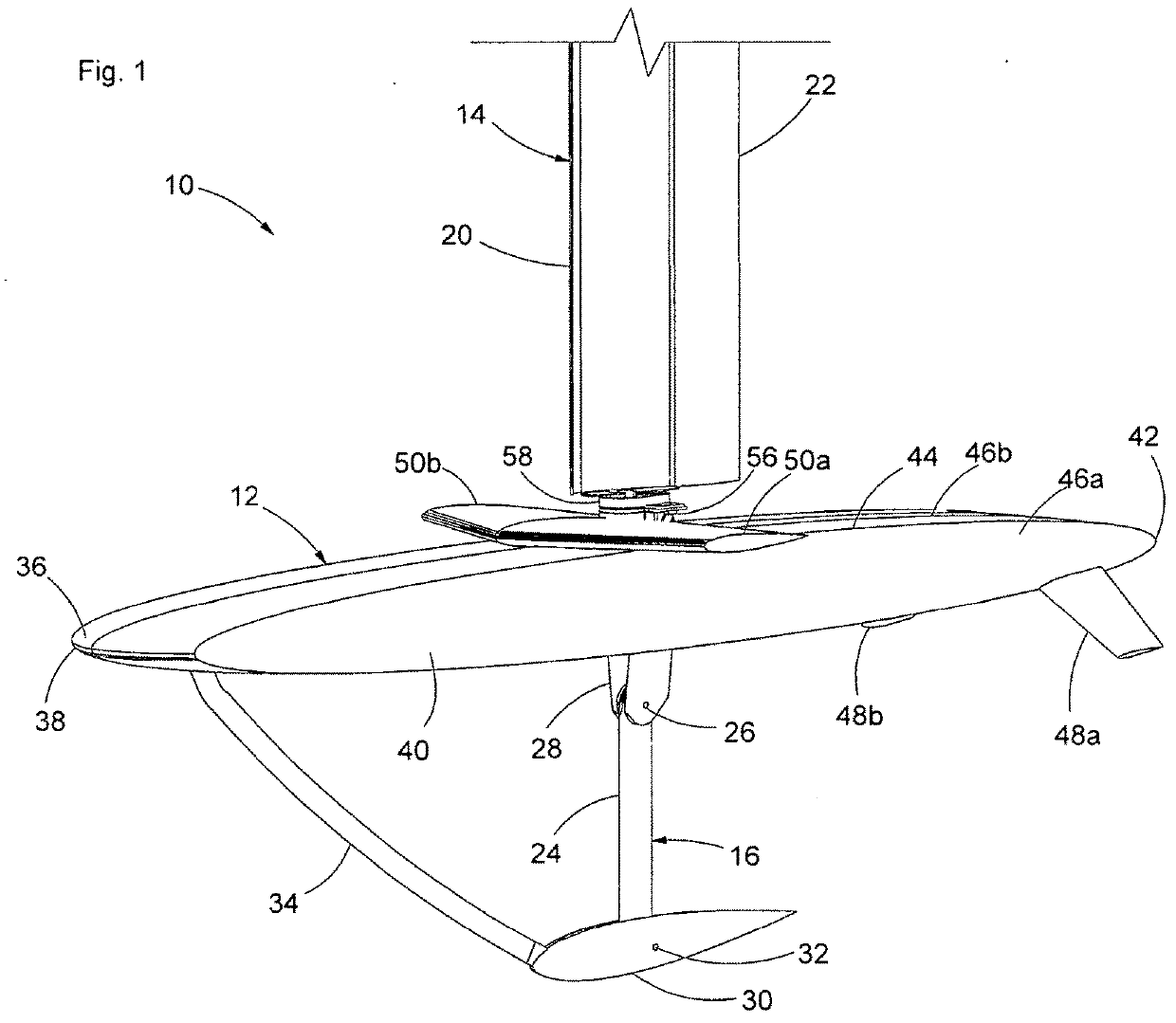
[0042]As will be described in greater detail below, the present invention provides a wind-powered vessel that is configurable for efficient operation in either surfaced or submerged modes. The vessel is eminently suited to unmanned, autonomous or semi-autonomous operation, however, it is envisioned that some embodiments may be configured to carry crew and / or other personnel.

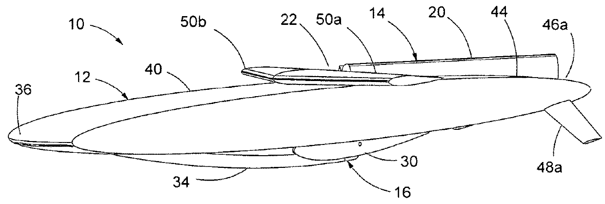
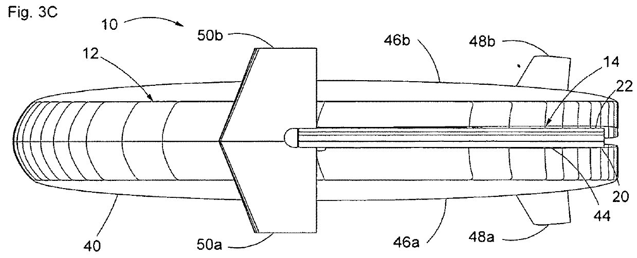
[0043]Accordingly, FIG. 1 shows a submersible vessel 10 in accordance with the present invention. As can be seen the vessel includes a main hull assembly 12 to which are mounted a wing assembly 14 and keel assembly 16. To configure the vessel for surface operation, as shown in FIG. 1, a deployment mechanism housed within the hull assembly 12, as will be described in greater detail below, is actuated to raise the wing assembly 14 and concurrently lower the keel assembly 16, so that in combination the wing and keel assemblies allow the vessel to employ wind-powered propulsion and also have the stability and other c...


PUM


Abstract

A submersible vessel having wing and keel assemblies that are extendable for wind-powered surface operation and retractable to reduce drag for submerged operation or to place the vessel in a more compact configuration. A deployment mechanism including an actuator and linkage pivots the wing and keel assemblies-simultaneously between the deployed and retracted configuration. The vessel may have first and second pressure hulls flanking the wing and keel assemblies. A drive mechanism including a motor and a gear train employing pulley-and-cable assemblies rotates either the wing and flap together such that the flap angle relative to the wing is constant, or to change the flap angle relative to the wing with the wing angle of incidence held constant. The invention also provides a retractable wind-powered propulsion apparatus that is mountable to the hull assembly of a submersible or non-submersible vessel.

Description

RELATED CASES[0001]This application claims the benefit of Provisional Patent Application Ser. No. 62 / 231,164 filed Jun. 25, 2015.BACKGROUNDa. Field of the Invention[0002]The present invention relates generally to submersible vessels, and, more particularly, to a wind-powered submersible vessel having wing and keel assemblies that are retractable for submerged operation of the vessel.b. Related Art[0003]Submersible vessels are waterborne craft capable of surfaced or submerged operation, in a marine environment or other body of water. As is well known, submersible vessels enjoy many advantages for both military and civilian functions, including reduced detectability, avoidance of adverse weather and surface traffic, and the ability to approach / investigate underwater targets, amongst others.[0004]Historically, submersible vessels have taken the form of maimed submarines, most commonly using diesel electric or nuclear propulsion systems. The construction and operating costs inherent in ...

Claims


Application Information

Patent Timeline
Patent Type & Authority Applications(United States)
IPC IPC(8): B63G8/00B63H9/06B63G8/08B63G8/04B63B41/00B63G8/20
CPCB63G8/001B63H9/0657B63G8/08B63B2041/003B63B41/00B63G8/20B63G8/04B63H9/0635B63H9/061Y02T70/5236Y02E70/30B63H9/067
Inventor MCCLURE, VANCE E.TODTER, CHRIS G.
Owner OCEAN AERO
Why Eureka
Try Eureka