

Luminous keyboard
- Summary
- Abstract
- Description
- Claims
- Application Information
AI Technical Summary
Benefits of technology
Problems solved by technology
Method used
Image

Examples
Embodiment Construction
[0022]For overcoming the drawbacks of the conventional technology, the present invention provides a luminous keyboard. The structure of the luminous keyboard will be described as follows.
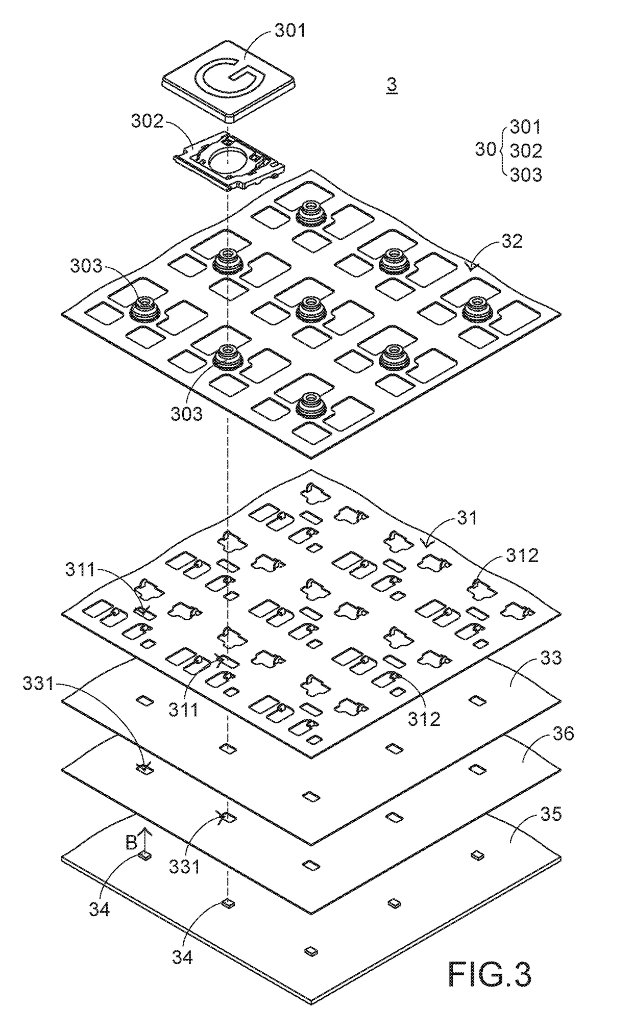
[0023]FIG. 3 is a schematic exploded view illustrating a portion of a luminous keyboard according to a first embodiment of the present invention. As shown in FIG. 3, the luminous keyboard 3 comprises plural key structures 30, a supporting plate 31, a switch circuit board 32, a light guide plate 33, plural top-view light-emitting elements 34, an illumination circuit board 35 and a reflecting element 36. For succinctness, only one key structure 30 is shown in FIG. 3. Each top-view light-emitting element 34 is aligned with one key structure 30. The plural key structures 30 are exposed outside the luminous keyboard 3. The supporting plate 31 is located under the plural key structures 30 and connected with the plural key structures 30. Moreover, the supporting plate 31 comprises plural supporting plate o...
PUM
 Abstract
Description
Claims
Application Information