Luminous keyboard

Inactive Publication Date: 2016-11-15
PRIMAX ELECTRONICS LTD
View PDF4 Cites 5 Cited by
  • Summary
  • Abstract
  • Description
  • Claims
  • Application Information

AI Technical Summary

Benefits of technology

The present invention aims to provide a luminous keyboard that has better uniformity of lighting.

Problems solved by technology

In other words, the luminous uniformity of the conventional luminous keyboard 2 is unsatisfied.

Method used


Image

  • Luminous keyboard
  • Luminous keyboard
  • Luminous keyboard

Examples


Embodiment Construction

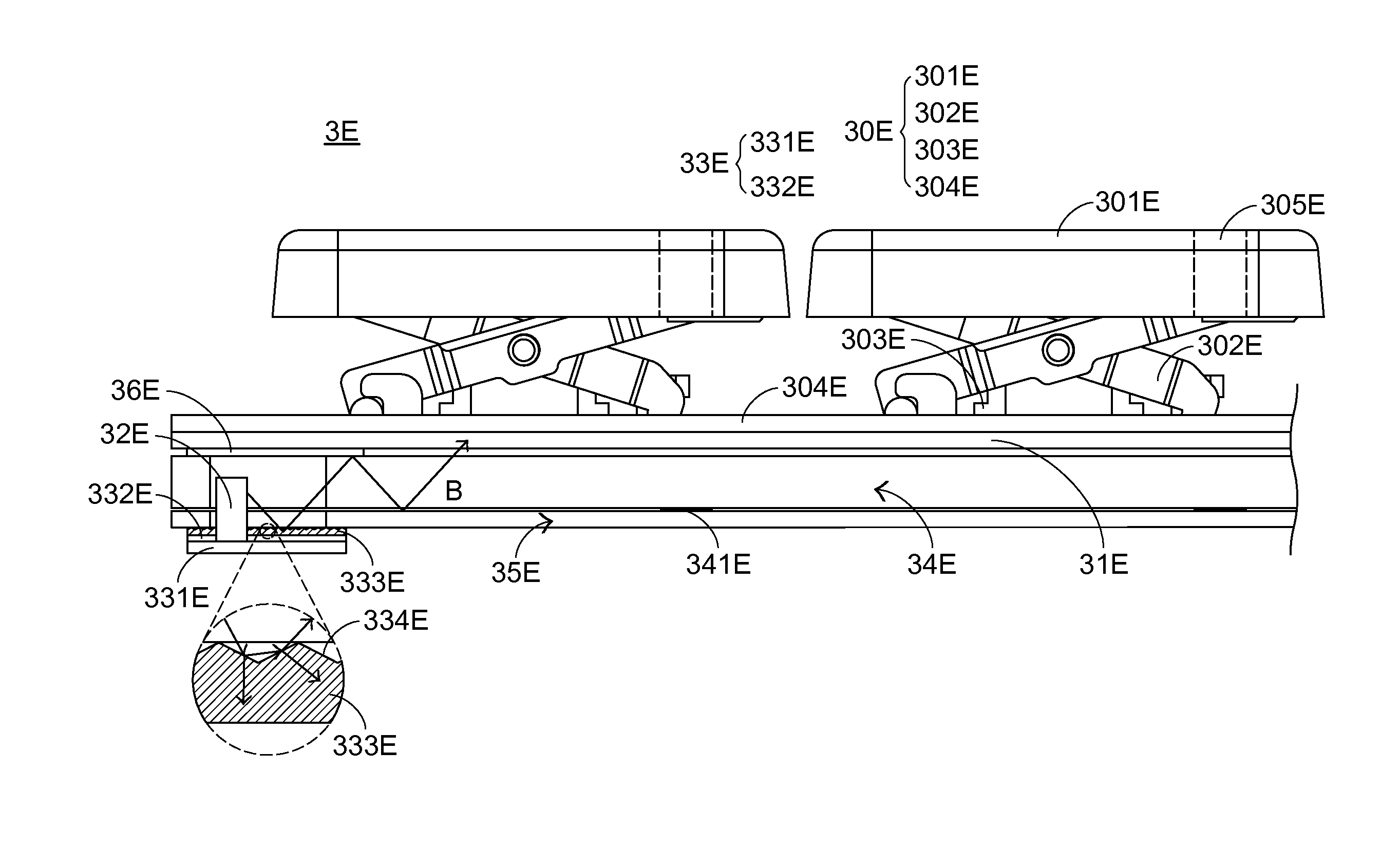
[0032]For overcoming the drawbacks of the conventional luminous keyboard, the present invention provides an improved luminous keyboard.

[0033]First of all, the structure of the luminous keyboard of the present invention will be illustrated as follows. FIG. 3 is a schematic cross-sectional view illustrating the structure of a luminous keyboard according to a first embodiment of the present invention. As shown in FIG. 3, the luminous keyboard 3A comprises a keypad module 30A, a supporting plate 31A, plural light-emitting elements 32A, an illumination circuit board 33A, a light guide plate 34A, a reflecting plate 35A and a light-shading plate 36A. For clarification and brevity, only one light-emitting element 32A is shown in the drawing. The keypad module 30A is exposed to a top surface of the luminous keyboard 3A. The keypad module 30A comprises plural keycaps 301A, plural connecting elements 302A, plural elastic elements 303A and a switch circuit member 304A. Each of the plural keycap...


PUM


Abstract

A luminous keyboard includes a keypad module, plural light-emitting elements, an illumination circuit board and a light guide plate. The illumination circuit board has a light amount control structure. The light amount control structure is disposed on a circuit board main body or a protective layer of the illumination circuit board, and arranged between the light guide plate and the illumination circuit board. When the plural light-emitting elements emit light beams to the illumination circuit board, the light beams are projected on the light amount control structure, and the reflected fraction of the light beams is reduced. Since the light beams are not very centralized, the problem of generating bright spots will be diminished.

Description

FIELD OF THE INVENTION[0001]The present invention relates to a keyboard, and more particularly to a luminous keyboard with an illuminating function.BACKGROUND OF THE INVENTION[0002]Generally, the widely-used peripheral input device of a computer system includes for example a mouse device, a keyboard, a trackball device, or the like. Via the keyboard, characters and symbols can be inputted into the computer system directly. As a consequence, most users and most manufacturers of input devices pay much attention to the development of keyboards.[0003]FIG. 1 is a schematic top view illustrating the outer appearance of a conventional keyboard. As shown in FIG. 1, there are plural keys 10 on a surface of the conventional keyboard 1. These keys 10 are classified into several types, e.g. ordinary keys 101, numeric keys 102 and function keys 103. When one of these keys 10 is depressed by the user's finger, a corresponding signal is issued to the computer, and thus the computer executes a func...

Claims


Application Information

Patent Timeline
IPC IPC(8): F21V7/04H01H13/83H01H13/7065F21V8/00
CPCH01H13/83H01H13/7065H01H2219/036H01H2205/002G02B6/0021G02B6/0011G02B6/0023G02B6/0025G02B6/0035G02B6/0068G02B6/0083H01H3/125H01H2219/06H01H2219/062
Inventor CHEN, CHUNG-YUAN
Owner PRIMAX ELECTRONICS LTD
Why Eureka
Try Eureka