Light guiding unit and backlight assembly having the same

a technology of light guiding unit and backlight assembly, which is applied in the direction of light guiding plate, lighting and heating apparatus, planar/plate-like light guides, etc. it can solve the problems of increasing the weight of the screen display device, affecting the uniform distribution of light from the light emitting diodes, and many of the advantages of not applying, so as to reduce the number of point light sources, reduce the thickness of the backlight assembly, and increase luminance uniformity

Inactive Publication Date: 2007-07-26
SAMSUNG ELECTRONICS CO LTD
View PDF4 Cites 60 Cited by
  • Summary
  • Abstract
  • Description
  • Claims
  • Application Information

AI Technical Summary

Benefits of technology

[0018]According to the present invention, the number of the point light sources is decreased in the direct illumination type backlight assembly. In addition, luminance uniformity is increased, and thickness of the backlight assembly is decreased.

Problems solved by technology

However, many of these advantages do not apply when the screen size exceeds a critical size.
For example, when light emitting diodes are on the side surface of a large screen display device, the light from the light emitting diodes is not uniformly distributed in the light guiding plate, at least in part because there is a special limitation as to the number of light emitting diodes that can be included.
In addition, the thickness of the light guiding plate increases when the screen size becomes large, also increasing the weight of the screen display device.
However, the direct-illumination type backlight assembly is not without its disadvantages.

Method used


Image

  • Light guiding unit and backlight assembly having the same
  • Light guiding unit and backlight assembly having the same
  • Light guiding unit and backlight assembly having the same

Examples


Embodiment Construction

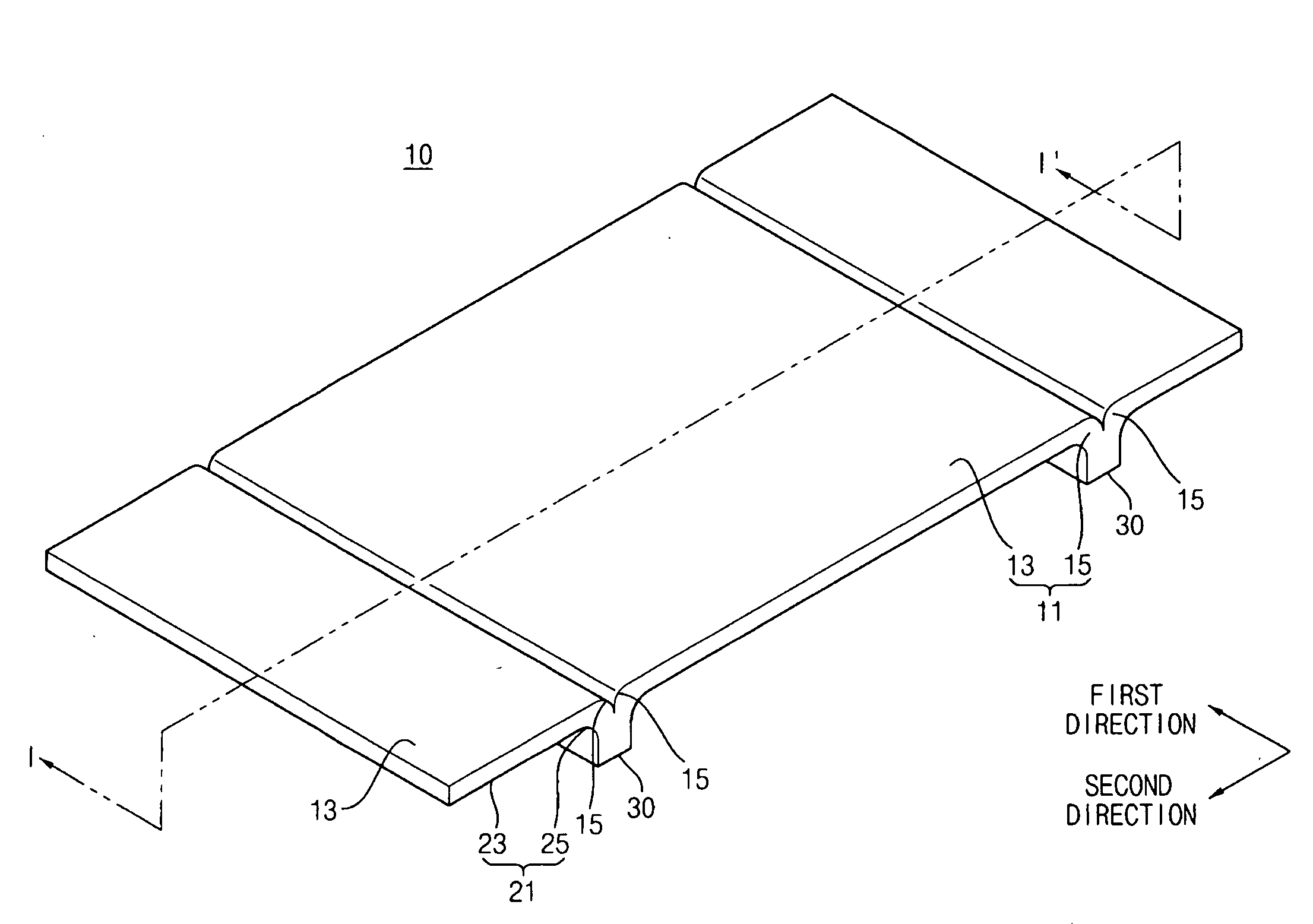
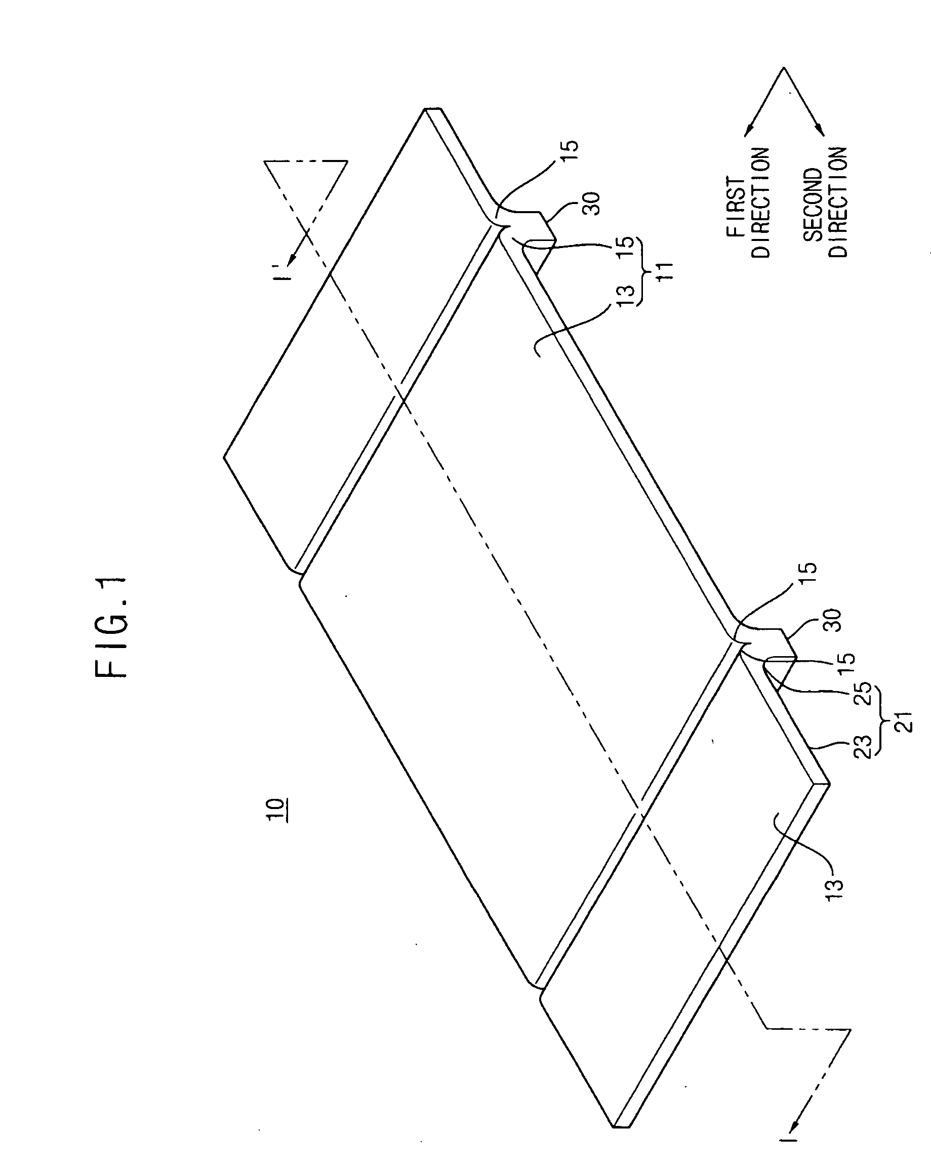
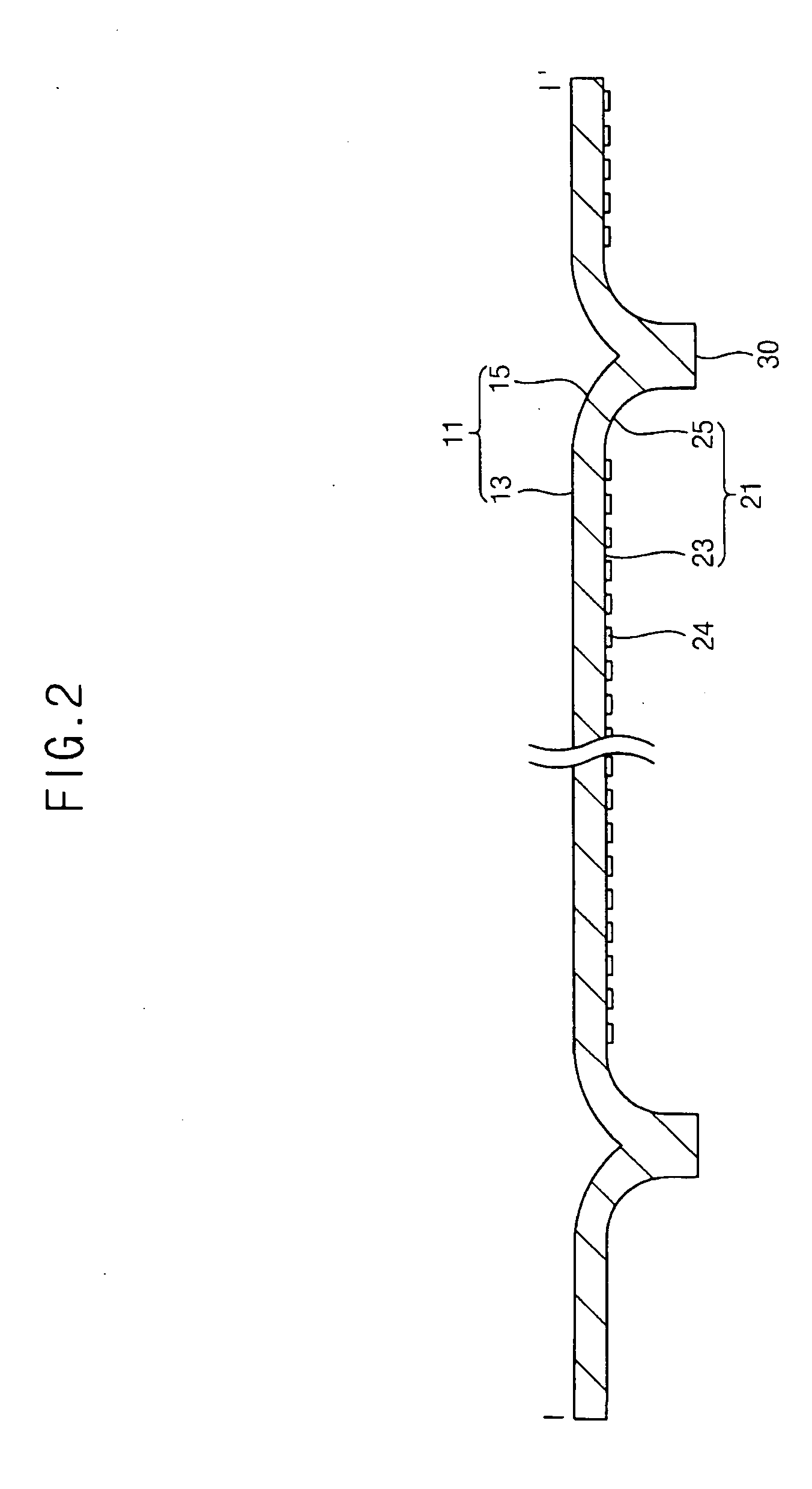
[0042]The invention is described more fully hereinafter with reference to the accompanying drawings, in which embodiments of the invention are shown. This invention may, however, be embodied in many different forms and should not be construed as limited to the embodiments set forth herein. Rather, these embodiments are provided so that this disclosure will be thorough and complete, and will fully convey the scope of the invention to those skilled in the art. In the drawings, the size and relative sizes of layers and regions may be exaggerated for clarity.

[0043]It will be understood that when an element or layer is referred to as being “on,”“connected to” or “coupled to” another element or layer, it can be directly on, connected or coupled to the other element or layer or intervening elements or layers may be present. Like numbers refer to like elements throughout. As used herein, the term “and / or” includes any and all combinations of one or more of the associated listed items.

[0044]...


PUM


Abstract

A light guiding unit that is capable of reducing the thickness of a backlight assembly and operating with fewer light sources is presented. The light guiding unit includes a first surface, a second surface and a light incident surface. The first surface includes a light exiting surface and an upper guiding curved surface that is recessed with respect to the light exiting surface. The second surface includes an opposite surface that is substantially parallel to the light exiting surface and a lower guiding curved surface recessed on the opposite surface toward the first surface, the lower guiding curved surface being positioned along the upper guiding curved surface. The light incident surface is formed on an end portion of the lower guiding curved surface.

Description

CROSS-REFERENCE TO RELATED APPLICATIONS[0001]The present application claims priority from Korean Patent Application No. 2006-06718 filed on Jan. 23, 2006, the disclosure of which is incorporated herein by reference in its entirety.BACKGROUND OF THE INVENTION[0002]1. Field of the Invention[0003]The present invention relates to a light guiding unit and a backlight assembly having the light guiding unit. More particularly, the present invention relates to a light guiding unit for a direct illumination type backlight assembly having a light emitting diode and a backlight assembly that uses the light guiding unit.[0004]2. Description of the Related Art[0005]A liquid crystal display (LCD) device, in general, is used in personal computers, laptop computers, automobile navigation systems, television receiver sets, etc., to convert information in electrical signals into visual images. The LCD device has advantageous characteristics such as light weight, thinness, low driving voltage requirem...

Claims


Application Information

Patent Timeline
Patent Type & Authority Applications(United States)
IPC IPC(8): F21V7/04H01L33/50
CPCG02B6/0016G02B6/0018G02F1/133611G02B6/0078G02F1/133603G02B6/0043E03F3/046E03F3/06E03F5/06
Inventor SHIM, SUNG-KYUHWANG, IN-SUNHWANG, SEONG-YONGCHO, JOO-WOAN
Owner SAMSUNG ELECTRONICS CO LTD
Why Eureka
Try Eureka