Dressing method of cutting blade

a cutting blade and dressing technology, applied in the field of dressing methods of cutting blades, can solve the problems of increasing the area of cutting the dressing board, increasing the wear of the cutting blade tip, and needing many dressing boards, so as to reduce the occurrence of the region of roundness generated by the dressing, increase the number of times of cutting devoted to dressing one cutting blade, and reduce the effect of cutting tim

Active Publication Date: 2019-07-04
DISCO CORP
View PDF0 Cites 3 Cited by
  • Summary
  • Abstract
  • Description
  • Claims
  • Application Information

AI Technical Summary

Benefits of technology

[0005]In the dressing, when the depth of cutting of the cutting blade into the dressing board becomes larger, the wear of the tip of the cutting blade increases. Thus, this tip changes into a shape having a curved surface and a rounded region (hereinafter, referred to also as region of roundness) is generated at the tip of the cutting blade more readily. For this reason, by repeatedly carrying out a step in which the cutting blade is caused to shallowly cut in...

Problems solved by technology

In the dressing, when the depth of cutting of the cutting blade into the dressing board becomes larger, the wear of the tip of the cutting blade increases.
However, the area of the cutting of the dressing board enlarges as the number of times of cutting devoted to dressing one cutting blade increases.
That is, there is...

Method used


Image

  • Dressing method of cutting blade
  • Dressing method of cutting blade
  • Dressing method of cutting blade

Examples


Embodiment Construction

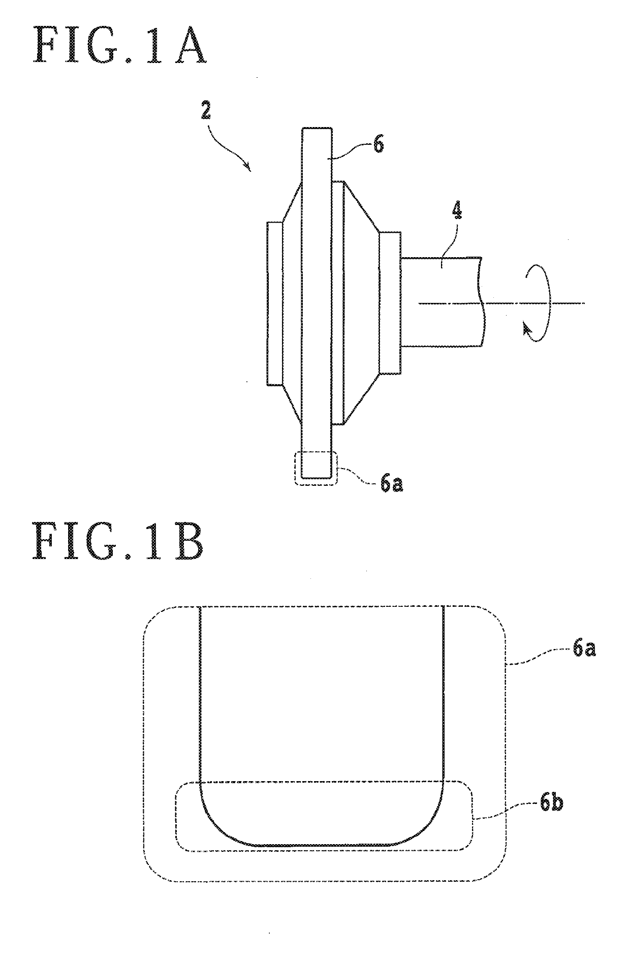
[0022]An embodiment according to one aspect of the present invention will be described with reference to the accompanying drawings. First, a configuration example of a cutting unit according to the present embodiment will be described. FIG. 1A is a side view schematically depicting a configuration example of a cutting unit 2. The cutting unit 2 includes a spindle 4 serving as a rotation axis. A cutting blade 6 with a circular ring shape is mounted to one end side of the spindle 4. For example, the cutting blade 6 can be formed by fixing diamond abrasive grains by a metal, resin, or nickel plating. Dressing of the cutting blade 6 is carried out by rotating the spindle 4 and causing the cutting blade 6 to cut into a dressing board to be described later.

[0023]FIG. 1B is an enlarged view of a region 6a of the tip of the cutting blade 6. Through repetition of cutting of a workpiece by use of the cutting blade 6, the corners of the tip of the cutting blade wear off and a rounded region (r...


PUM

PropertyMeasurementUnit
Shapeaaaaaaaaaa

Abstract

A dressing method of a cutting blade includes a first cutting step of causing the cutting blade to cut into a dressing board held by a holding surface of a chuck table with a cutting depth that does not surpass the length of the region of roundness in the radial direction of the cutting blade to form a cut groove in the dressing board, and a second cutting step of causing the cutting blade to further cut into the groove bottom of the cut groove formed in the first cutting step with a cutting depth that does not surpass the length of the region of roundness in the radial direction of the cutting blade to carry out cutting on the groove bottom with tracing of the cut groove.

Description

BACKGROUND OF THE INVENTIONField of the Invention[0001]The present invention relates to a dressing method of a cutting blade that cuts a workpiece such as a semiconductor wafer.Description of the Related Art[0002]When a plate-shaped workpiece typified by a semiconductor wafer is divided into plural chips, a cutting apparatus including a ring-shaped cutting blade is used for example. By relatively moving the cutting blade and the workpiece while the cutting blade rotated at high speed is caused to cut into the workpiece, the workpiece can be cut along the path of this movement.[0003]Before a workpiece is cut by using a cutting blade, dressing for arranging the shape of the cutting blade concentrically with a spindle serving as a rotation axis (shaping, roundness generation) and eliminating loading, dulling, and so forth of the blade edge is carried out by causing the cutting blade to cut into a dressing board. This corrects a rounded shape or the like of the tip of the cutting blade ...

Claims


Application Information

Patent Timeline
IPC IPC(8): B24B3/36
CPCB24B3/36B24B41/00B24B27/0608B24B53/04B24B53/12H01L21/67092H01L21/78B24B3/46B23D63/14
Inventor KOMATSU, ATSUSHI
Owner DISCO CORP
Why Eureka
Try Eureka