Rotating hanging light connector

Active Publication Date: 2019-07-18
PUREEDGE LIGHTING LLC
View PDF0 Cites 0 Cited by
  • Summary
  • Abstract
  • Description
  • Claims
  • Application Information

AI Technical Summary

Benefits of technology

[0006]There is disclosed herein an improved lighting system which avoids the disadvan

Problems solved by technology

That is, lighting is no longer necessarily functional or aesthetic, it can be both.
For example, existing hanging light structures tend to have limited versatility due, in part, to having a fixed lighting direction.
That is, once

Method used


Image

  • Rotating hanging light connector
  • Rotating hanging light connector
  • Rotating hanging light connector

Examples


Example

[0029]While this invention is susceptible of embodiments in many different forms, there is shown in the drawings and will herein be described in detail at least one preferred embodiment of the invention with the understanding that the present disclosure is to be considered as an exemplification of the principles of the invention and is not intended to limit the broad aspect of the invention to any of the specific embodiments illustrated.

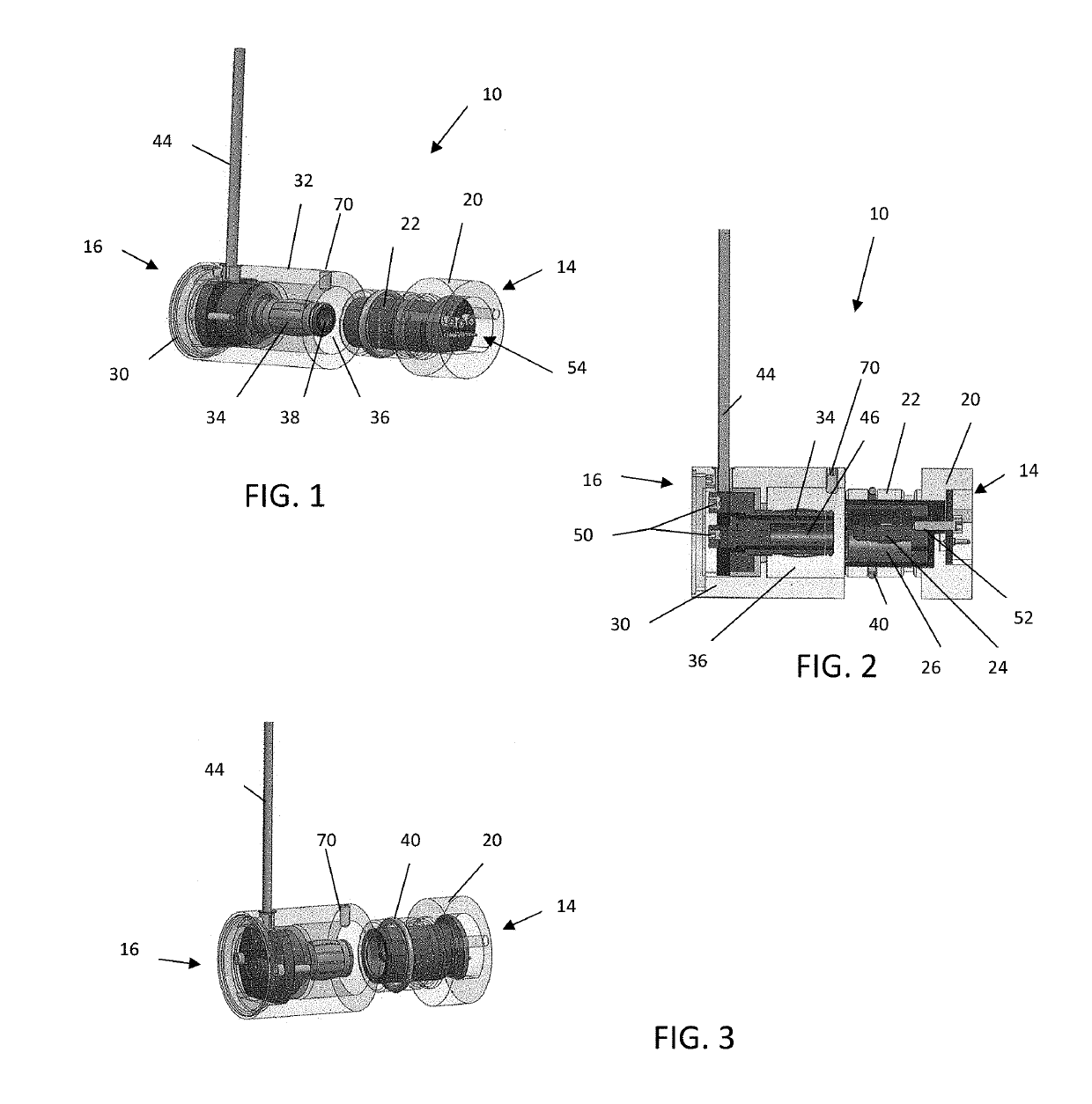
[0030]Referring to FIGS. 1-13, there is illustrated a hanging light system, generally designated by the numeral 10. The particular illustrated lighting system 10 is for tube lights. In fact, while all the embodiments illustrated are directed to LED tube lights, it should be understood that the principles of the invention may be more broadly applied to use with other light sources, as well.

[0031]As can be seen in FIGS. 1-3, a key component of the lighting system 10 is the connection system 12 used to couple a light source to a power source. This conne...


PUM


Abstract

A lighting system having a light element, a first connector, a second connector and an electrically coupled power source is described. The light element has a light source, a surface for emitting light. The first connector is fixed to an end of the light element and includes a cylindrical housing defining a cylindrical cavity, the cylindrical cavity having a plug positioned therein, the plug being electrically coupled to the light source within the light element, while the second connector couples to the first connector and has an outer housing and a cylindrical cavity defined therein. The first cylindrical housing is configured to frictionally engage an inner wall of the second cylindrical cavity when connected. A second plug positioned within the second cylindrical cavity has a third cylindrical cavity defined therein, wherein the second plug is configured to frictionally engage an inner wall of the cylindrical cavity and the plug is configured to frictionally engage an inner wall within the third cylindrical cavity. The power source is electrically coupled to the plug through connection with the second plug to power the light source. The first connector is capable of being rotated when coupled to the second connector, preferably a full 360 degrees.

Description

TECHNICAL FIELD OF THE INVENTION[0001]The present invention relates to modular lighting systems. Specifically, the disclosed lighting system relates to a lighting connector system used for creating and powering unique lighting structures.BACKGROUND OF THE INVENTION[0002]Unique lighting systems are beginning to bridge the gap between functional lighting and aesthetic lighting. That is, lighting is no longer necessarily functional or aesthetic, it can be both. The use of LEDs has played a big role in this advancement of the field of lighting. LEDs have significant advantages over incandescent and fluorescent lighting, including having a much lower power requirement, far less heat radiation, higher energy efficiency, longer life expectancy, and greater durability.[0003]These same advantages, as well as others, make the use of LEDs the preferred lighting system for not only appliances, electronics and vehicles, but also for commercial as well as residential buildings. Lighting structure...

Claims


Application Information

Patent Timeline
IPC IPC(8): F21V23/06H01R24/38F21S8/06F21K9/272F21V21/005F21K9/275
CPCF21V23/06H01R24/38F21S8/061F21K9/272F21V21/005F21K9/275F21Y2115/10F21Y2103/10F21S4/28F21V21/30F21K9/65H01R33/942H01R35/04
Inventor KAY, GREGORY L.O'SHEA, JAMES E.
Owner PUREEDGE LIGHTING LLC
Why Eureka
Try Eureka