Injector nozzle coking compensation strategy

Active Publication Date: 2014-01-02
INT ENGINE INTPROP CO LLC
View PDF2 Cites 2 Cited by
  • Summary
  • Abstract
  • Description
  • Claims
  • Application Information

AI Technical Summary

Benefits of technology

[0007]There is disclosed herein an improved fuel injection nozzle system and control strategy which avoids the disadvantages of prior devices while affording additional struc

Problems solved by technology

Unfortunately, HE nozzles also have a greater propensity to exhibit coking, or injector spray hole fouling, which is the deposition of coked fuel layers on the orifice wall (internal) and on the outside surface of the nozzle tip (external).
As rated injection pressures of new injection systems increase to further provide emission be

Method used


Image

  • Injector nozzle coking compensation strategy
  • Injector nozzle coking compensation strategy
  • Injector nozzle coking compensation strategy

Examples


Example

[0020]While this invention is susceptible of embodiments in many different forms, there is shown in the drawings and will herein be described in detail a preferred embodiment of the invention with the understanding that the present disclosure is to be considered as an exemplification of the principles of the invention and is not intended to limit the broad aspect of the invention to embodiments illustrated.

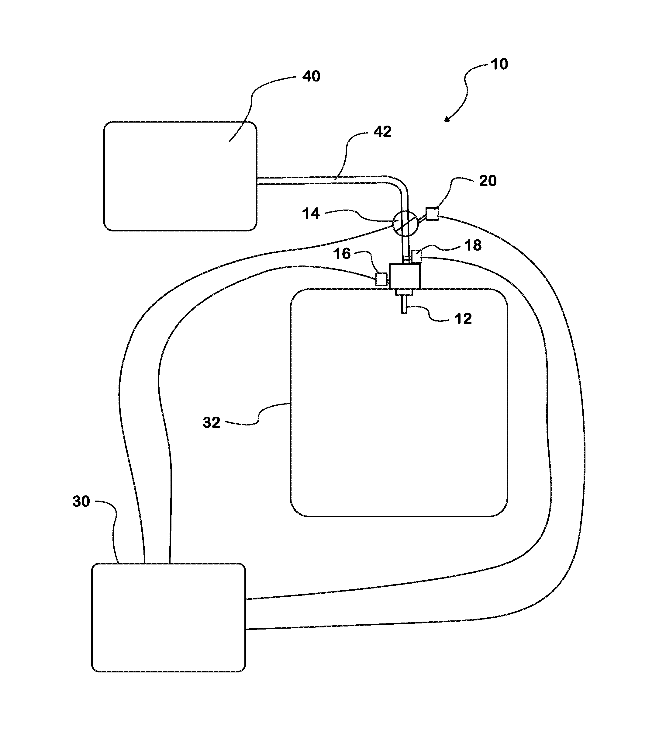
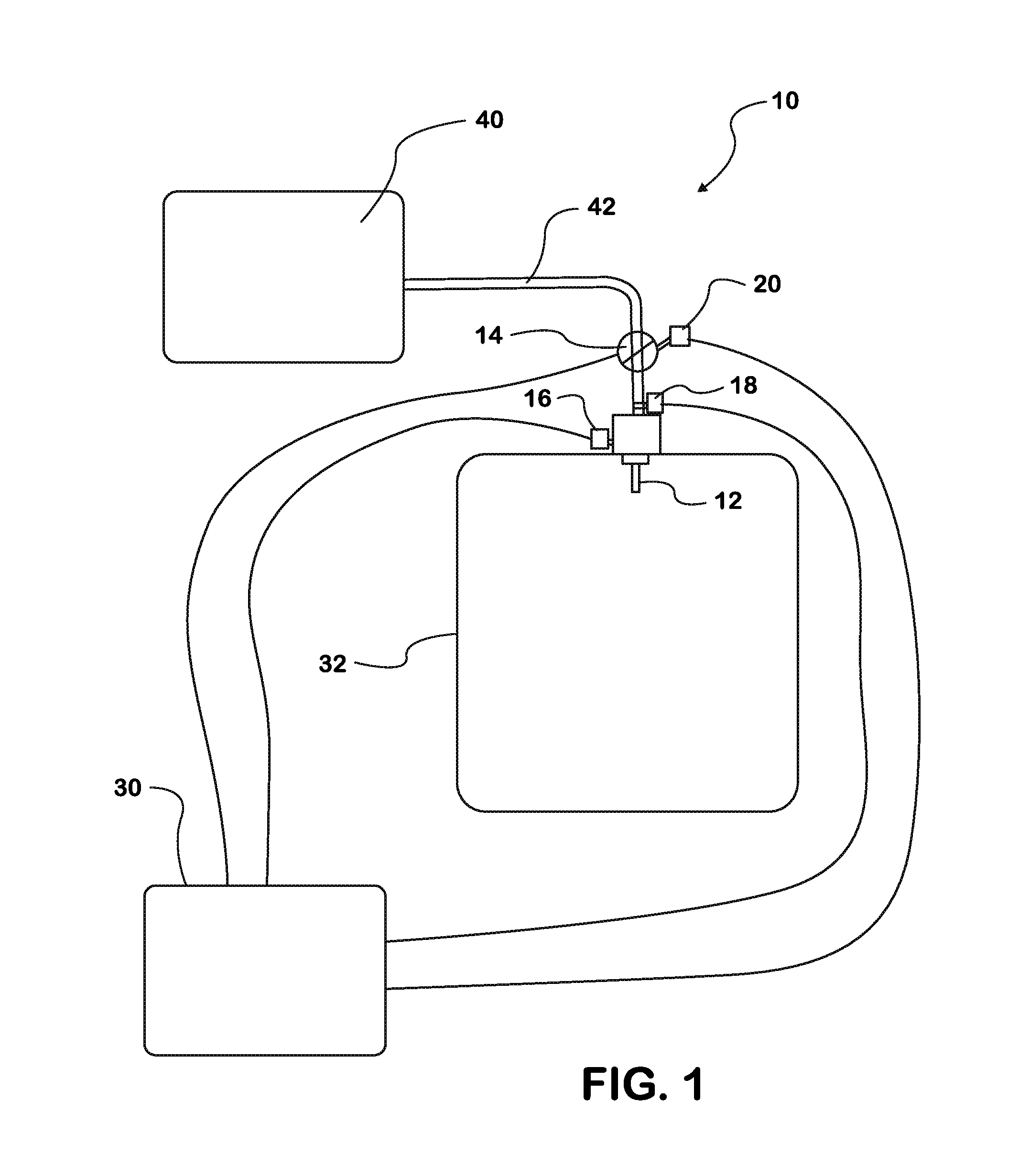
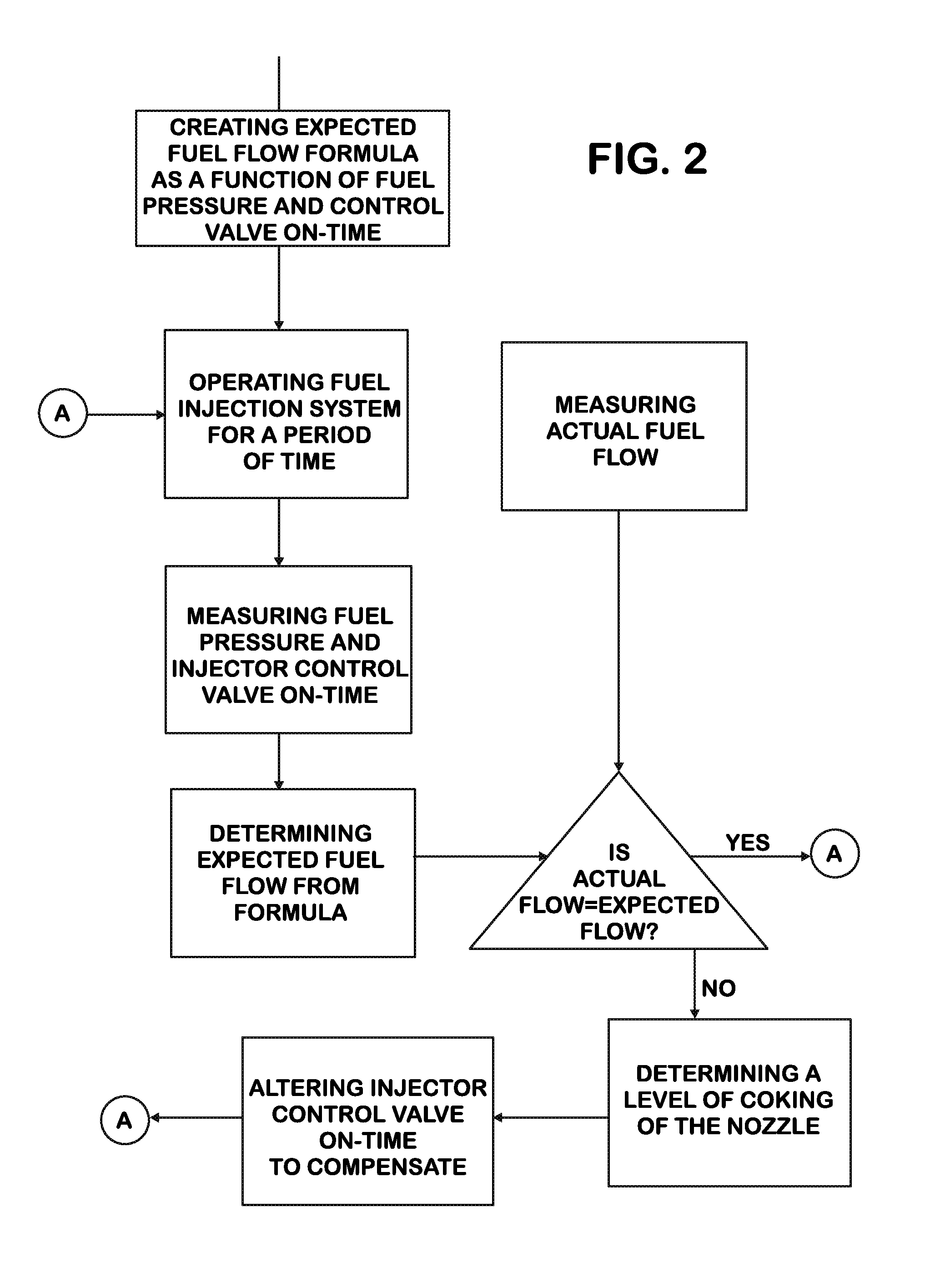
[0021]Referring to FIGS. 1-3, there is illustrated embodiments of both methods for creating an injector nozzle coking compensation strategy and a fuel injection nozzle system, generally designated by the numeral 10. The methods and systems are not limited to any particular type of injection nozzle, though high-efficiency nozzles are particularly useful.

[0022]Generally speaking, with reference to the drawing of FIG. 1, the fuel injection system 10 includes a fuel source 40, a fuel injection nozzle 12, a control valve 14, a fuel flow rate sensor 16, a pressure sensor 18, a control v...


PUM


Abstract

Systems and methods for compensating for nozzle coking in fuel injection system include creating expected fuel flow rate formula for selected fuel injection nozzle, operating selected fuel injection nozzle for a time, measuring fuel pressure and injector control valve on-time of fuel injection nozzle during operation, determining expected fuel flow ate for measured fuel pressure and injector control valve on-time, measuring actual fuel flow rate of fuel injection nozzle, determining coking condition of fuel injection nozzle, and automatically altering injector control valve on-time to compensate. Expected fuel flow rate formula is determined as function of fuel pressure and injector control valve on-time, while actual fuel flow rate is measured by flow rate sensor attached to injection system. Sometimes, coking condition determination is based on difference between actual fuel flow rate and expected flow rate. Compensation in control valve on-time is necessitated by deterioration in actual fuel flow to cylinder.

Description

TECHNICAL FIELD OF THE INVENTION[0001]The present device relates to a fuel-injection system using high-efficiency (HE) injection nozzles. Particularly, the present device relates to an a HE fuel-injection nozzle coking compensation strategy.BACKGROUND OF THE INVENTION[0002]Fuel systems typically employ multiple closed-nozzle fuel injectors to inject high pressure fuel into the combustion chambers of an engine. Each of these fuel injectors includes a nozzle assembly having a cylindrical bore with a nozzle supply passageway and a nozzle outlet. The efficiency of the nozzle outlet or orifice is a measure of how effectively the energy stored in the fuel as pressure is converted into kinetic energy. The greater the kinetic energy, the more the fuel is broken apart (atomized), improving combustion completeness and lowering soot. High-efficiency (HE) nozzles, i.e., those with the highest orifice efficiency, are desirable for emissions.[0003]Unfortunately, HE nozzles also have a greater pro...

Claims


Application Information

Patent Timeline
IPC IPC(8): F02D41/00
CPCF02D41/00F02D41/2467F02D2041/224F02D2200/0602F02D2200/0614F02M2200/247F02M2200/06F02M2200/24F02M57/005
Inventor KORENCHAN, JAMES E.
Owner INT ENGINE INTPROP CO LLC
Why Eureka
Try Eureka