Inkjet printing apparatus and control method of inkjet printing apparatus

Active Publication Date: 2019-08-29
CANON KK
View PDF4 Cites 1 Cited by
  • Summary
  • Abstract
  • Description
  • Claims
  • Application Information

AI Technical Summary

Benefits of technology

The inkjet printing apparatus described in this patent has a print head, tank, supply and collection flow paths, valves to control the flow of ink, an intra-tank vacuum pump, and a control unit to manage these components. The control unit performs two operations, one to remove ink from the ejection opening to the tank via the supply flow path and one to remove ink from the ejection opening to the collection flow path and tank via the supply flow path. The technical effects of this invention include improved inkjet printing efficiency and pressure reduction in the tank.

Problems solved by technology

However, in Document 1, there may be a case of requiring time for the process of pulling out ink into the ink container or a case of occurrence of remaining ink.
Furthermore, in Document 1, there is a possibility of occurrence of remaining ink in the head because a process of pulling out ink in one direction of the flow path is performed.

Method used


Image

  • Inkjet printing apparatus and control method of inkjet printing  apparatus
  • Inkjet printing apparatus and control method of inkjet printing  apparatus
  • Inkjet printing apparatus and control method of inkjet printing  apparatus

Examples


first embodiment

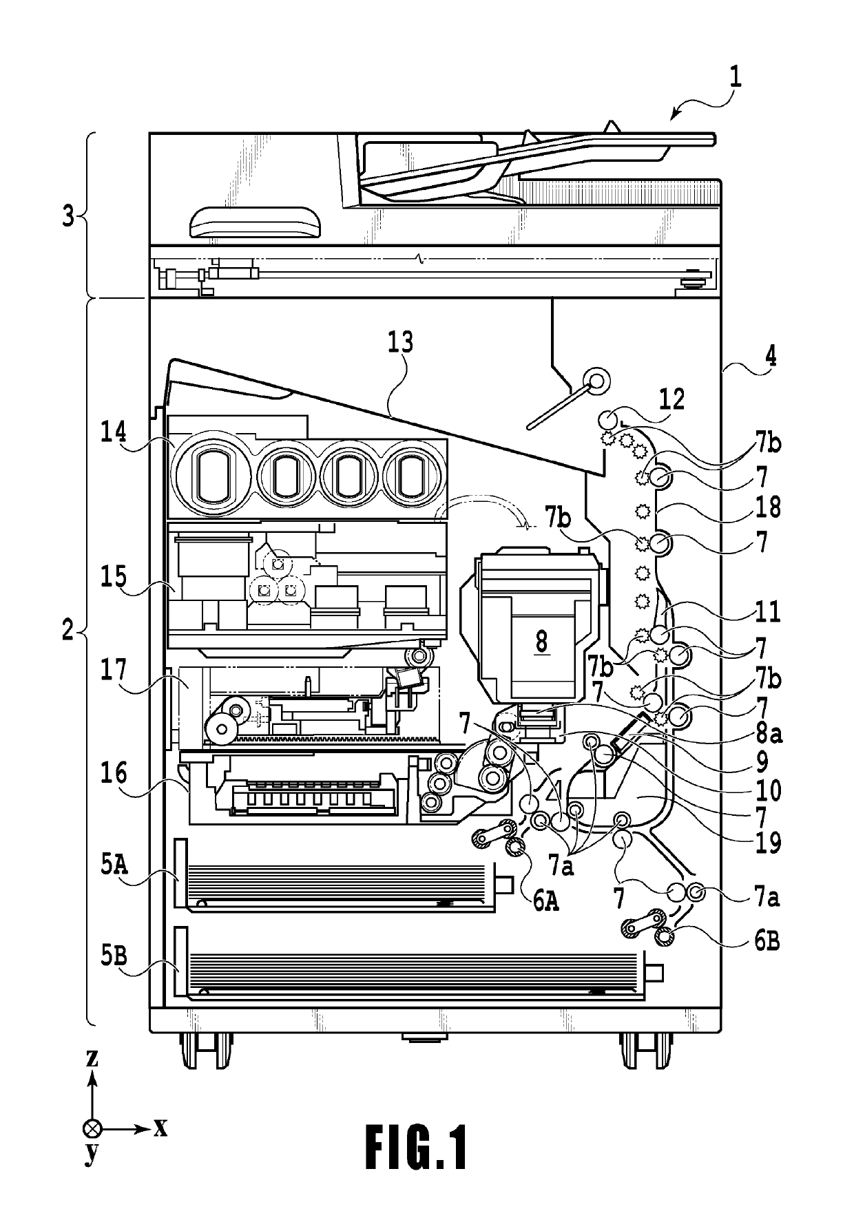
[0029]FIG. 1 is an internal configuration diagram of an inkjet printing apparatus 1 (hereinafter “printing apparatus 1”) used in the present embodiment. In the drawings, an x-direction is a horizontal direction, a y-direction (a direction perpendicular to paper) is a direction in which ejection openings are arrayed in a print head 8 described later, and a z-direction is a vertical direction.

[0030]The printing apparatus 1 is a multifunction printer comprising a print unit 2 and a scanner unit 3. The printing apparatus 1 can use the print unit 2 and the scanner unit 3 separately or in synchronization to perform various processes related to print operation and scan operation. The scanner unit 3 comprises an automatic document feeder (ADF) and a flatbed scanner (FBS) and is capable of scanning a document automatically fed by the ADF as well as scanning a document placed by a user on a document plate of the FBS. The present embodiment is directed to the multifunction printer comprising b...

second embodiment

[0089]In the present embodiment, an explanation is given of a mode in which, in a case where there is a connection unit (hereinafter referred to as a “joint”) between the head unit 8 and the ink supply unit 15 to connect the respective units, the head unit 8 is separated from the ink supply unit 15. In a case of replacing the head unit 8, the joint is released, and the head unit 8 and the ink supply unit 15 are separated from each other. In a case where the joint is released, ink may drip from the connection surface of the joint. In the present embodiment, an explanation is given of a mode for preventing ink from dripping at the time of releasing the joint as described above. Noted that explanations of the configurations similar to those explained in the first embodiment are omitted.

[0090]FIG. 15 is a diagram showing a state of the ink circulation system filled in with ink in the present embodiment. The joint J on the supply flow path C2 side is disposed on the downstream side (i.e....

modification example 1

[0096]Next, an explanation is given of a modification example of the second embodiment. In the mode as described above, an explanation has been given of a mode in which the vacuum pump P3 (i.e., intra-cap vacuum pump) that reduces pressure inside a cap is used as a negative pressure generating source for generating a negative pressure in the joint J. In the modification example, an explanation is given of a mode in which a negative pressure is generated in the joint J by use of the vacuum pump P0 (i.e., intra-tank vacuum pump) that reduces pressure in the sub-tank 151.

[0097]FIG. 19 is a diagram showing a flowchart of the modification example. Steps S1902, S1904, and S1906 are different as compared with the processing of FIG. 16. The different parts are explained below.

[0098]At Step S1902, the ink supply control unit 209 opens the head replacement valve V5 and the collection valve V4 (OPEN). At Step S1904, the ink supply control unit 209 generates a negative pressure by use of the va...


PUM


Abstract

An inkjet printing apparatus includes: a print head provided with an ejection opening surface; a tank; a supply flow path; a collection flow path; an intra-tank vacuum pump to reduce pressure inside the tank; and a control unit. The control unit performs a first operation and a second operation, the first operation causing the intra-tank vacuum pump to operate while a collection drive valve is closed, so as to pull out ink in a flow path which extends from the ejection opening to the supply flow path into the tank, the second operation causing the intra-tank vacuum pump to operate while a supply drive valve is closed, so as to pull out ink in a flow path which extends from the ejection opening to the collection flow path into the tank.

Description

BACKGROUND OF THE INVENTIONField of the Invention[0001]The present invention relates to an inkjet printing apparatus and a control method of the inkjet printing apparatus.Description of the Related Art[0002]An inkjet printing apparatus in which a circulation flow path connecting a print head and an ink container is adopted is known. Specification of U.S. Pat. No. 8,733,908 (hereinafter referred to as Document 1) discloses an inkjet printing apparatus including a print head 200, a print fluid line 380 serving as a flow path on the upstream side of the print head 200, and a closed loop 348 serving as a flow path on the downstream side of the print head 200 (numerals in Document 1 are attached for reference). Furthermore, a pump 378 for ink circulation is disposed in the flow path on the downstream side of the print head 200. Further, a valve 386 for controlling whether to stop ink circulation is disposed in the flow path on the upstream side of the print head 200. The valve 386 is als...

Claims


Application Information

Patent Timeline
IPC IPC(8): B41J2/175
CPCB41J2/17596B41J29/38B41J2/18B41J2/175
Inventor ARAI, RYOMASAEKI, TSUYOSHITOKISAWA, TOSHIAKIKOSUGE, JUNYA
Owner CANON KK
Why Eureka
Try Eureka