Hydrodynamic bearing device

Inactive Publication Date: 2005-09-15
NIDEC CORP
View PDF0 Cites 6 Cited by
  • Summary
  • Abstract
  • Description
  • Claims
  • Application Information

AI Technical Summary

Benefits of technology

[0017] The present invention is to solve the above described problems, and has an object to provide a hydrodynamic bearing device capable of inhibiting leakage of a working fluid such as oil outside a bearing and preventing reduction in radial bearing rigidity, and capable of keeping a gap between a thrust bearing and a radial bearing favorable and rotating stably without contact, and capable of keeping performance of the bearing favorable at low temperature.
[0019] In this construction, the pores existing on the surface of the sintered metal constructing the sleeve are impregnated with resin, metal or water glass and are cured, whereby the working fluid such as oil can be inhibited from leaking outside the bearing from the pores on the surface of the sleeve, reduction in pressure inside the bearing can be prevented and reduction in radial bearing rigidity can be prevented, thus making it possible to enhance reliability. By constructing the entire sleeve by the sintered metal, the gap between the thrust bearing and the radial bearing can be kept favorable and the number of components and assembly steps can be reduced.
[0020] Iron is used for the component of the metal particles which are to be the raw material of the sleeve constituted of the sintered metal so that the linear expansion coefficient of the shaft becomes larger than the linear expansion coefficient of the sleeve, and thereby, the gap between the sleeve and the shaft is widened at low temperature. Even when the viscosity of the oil becomes high at low temperature, the relative rotation of the shaft can be prevented from being slow, and increase in the electric current consumption at low temperature can be suppressed to the minimum in the motor or the like using this hydrodynamic bearing device.

Problems solved by technology

However, the hydrodynamic bearing device of the conventional construction as described above has the following problems.
However, the hydrodynamic bearing device with the above-described conventional construction has the following problems.
Since the operation of inserting and fixing the sleeve body 30 into the sleeve cover 31 is needed and the sleeve body 30 and the sleeve cover 31 are separately provided, there is the disadvantage that the number of components increases correspondingly.
Accordingly, in the motor using this hydrodynamic bearing device, electric current consumption increases at the low temperature.

Method used


Image

  • Hydrodynamic bearing device
  • Hydrodynamic bearing device
  • Hydrodynamic bearing device

Examples


first embodiment

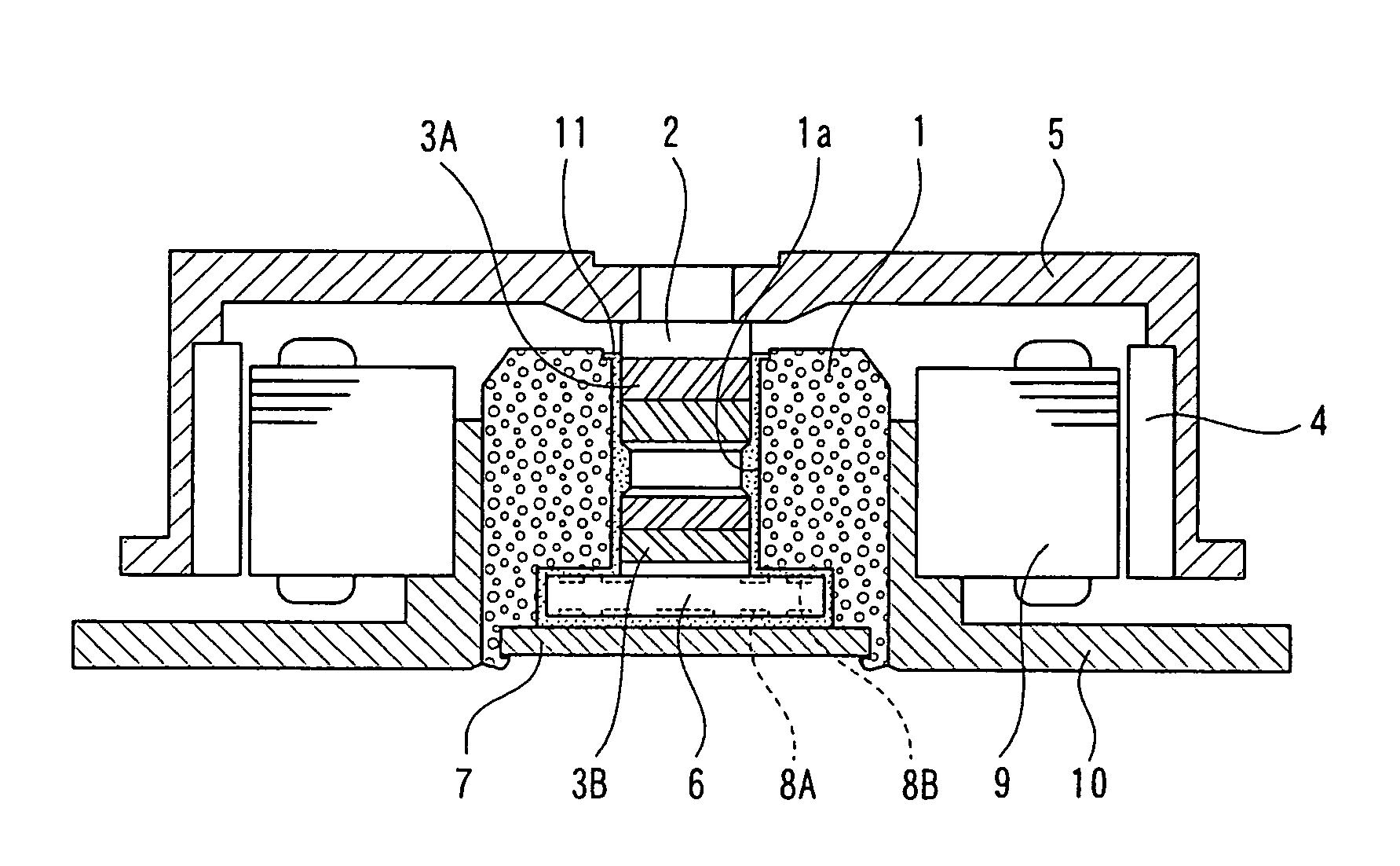
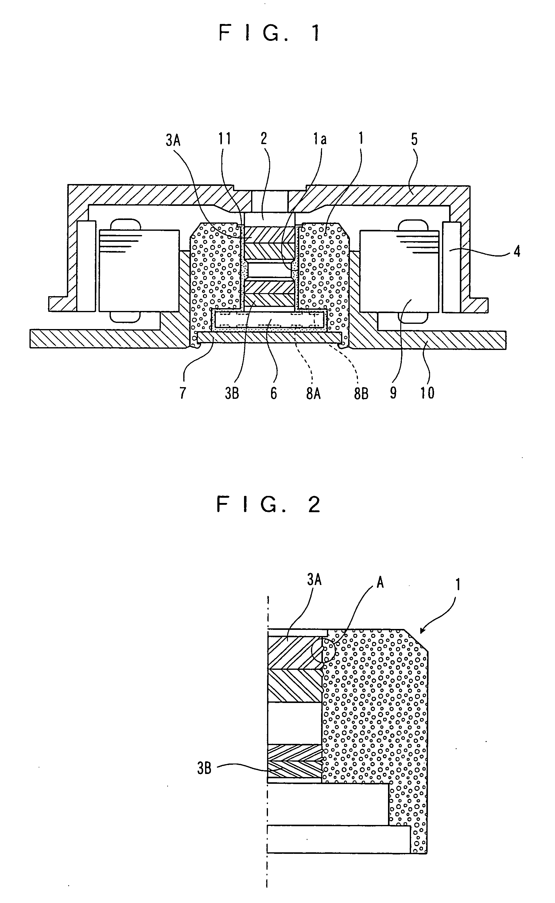
[0036]FIG. 1 is a sectional view of a hydrodynamic bearing device according to a first embodiment of the present invention. A shaft 2 is rotatably inserted into a bearing hole 1a of a sleeve 1, and a radial bearing surface having dynamic pressure generating grooves 3A and 3B constituted of pattern-shaped shallow grooves is provided at least one of an outer peripheral surface of the shaft 2 and an inner peripheral surface of the sleeve 1. A rotor hub 5 having a rotor magnet 4 in an inner periphery of its large diameter portion is mounted at one end (upper part in FIG. 1) side of the shaft 2, and a thrust flange 6 is integrally mounted at the other end (lower part in FIG. 1) side of the shaft 2 to be perpendicular to the shaft 2. A bearing surface at the lower end side of the thrust flange 6 opposes to a thrust plate 7, and the thrust plate 7 is fixed to the sleeve 1. A dynamic pressure generating groove 8A in a spiral or a herringbone pattern is formed on at least one of the surfaces...

second embodiment

[0052]FIG. 8 is a sectional view of a hydrodynamic bearing device according to a second embodiment of the present invention. A shaft 22 is rotatably inserted into a bearing hole 21a of a sleeve 21, and a radial bearing surface having dynamic pressure generating grooves 23A and 23B constructed by pattern-shaped shallow grooves is provided on at least one of an outer peripheral surface of the shaft 22 and an inner peripheral surface of the sleeve 21. A thrust bearing surface is formed at a lower end surface of the shaft 22 to be perpendicularly to the shaft 22, the thrust bearing surface is opposed to a thrust plate 24, the thrust plate 24 is fixed to the sleeve 21, a dynamic pressure generating groove 25 in a spiral or a herringbone pattern is formed on any one of the thrust bearing surface and the surface of the thrust plate 24, and a gap between the shaft 22 and the sleeve 21 and a gap between the shaft 22 and the thrust plate 24 are filled with oil 26 as the lubricant. The sleeve ...


PUM


Abstract

A hydrodynamic bearing device capable of inhibiting leakage of a working fluid to an outside of a bearing and preventing reduction in radial bearing rigidity, and capable of keeping a gap between a thrust bearing and a radial bearing favorable and rotating stably. The hydrodynamic bearing device includes a shaft relatively rotatably inserted into a bearing hole of a sleeve, a radial bearing surface having dynamic pressure generating grooves formed on at least one of an outer peripheral surface of the shaft and an inner peripheral surface of the sleeve, and a gap filled with a working fluid between the shaft and the sleeve. The shaft is made of high manganese chrome steel or stainless steel, and the sleeve is entirely made of sintered metal of metal particles including at least 60% by weight of iron or copper. Resin, metal or water glass is impregnated in pores on a surface of the sintered metal and cured. Thereby, leakage of the working fluid to the outside of the bearing from the sleeve can be inhibited, and reduction in the pressure inside the bearing can be prevented.

Description

FIELD OF THE INVENTION [0001] The present invention relates to a hydrodynamic bearing device using a dynamic pressure hydraulic bearing. The hydrodynamic bearing device of the present invention can be applied to a hydrodynamic bearing device especially suitable for motors or the like of a hard disc unit or the other disc units, but it can be applicable to the other units. The hydrodynamic bearing device of the present invention is especially suitable for the case using oil (lubricating oil) as a working fluid, but it is possible to apply the device to a hydrodynamic bearing device using air as a working fluid, and further it is also possible to apply the device to hydrodynamic bearing devices using gases other than air as the working fluid. BACKGROUND OF THE INVENTION [0002] In a recording apparatus or the like using a disc or the like, its memory capacity increases and the transferring speed of the data becomes high in recent years. Therefore, a bearing device used in this kind of ...

Claims


Application Information

Patent Timeline
IPC IPC(8): B25G3/02F16C17/10F16C33/12F16C33/20G11B19/20H02K5/167H02K7/08
CPCF16C17/107Y10S384/902F16C33/1025F16C2370/12
Inventor ASADA, TAKAFUMIHAMADA, TSUTOMUOHNO, HIDEAKITOKUNOU, YASUNORI
Owner NIDEC CORP
Why Eureka
Try Eureka