Connecting pipe

Inactive Publication Date: 2006-06-29
TOKAI RUBBER IND LTD
View PDF4 Cites 11 Cited by
  • Summary
  • Abstract
  • Description
  • Claims
  • Application Information

AI Technical Summary

Benefits of technology

[0039] And, as shown in Table 2 (Table 2 explains the press-fit performance and the sealing performance at varied braid angles under a certain diametrically enlarging rate of the rubber hose), in a reinforcing layer formed by braiding the reinforcing yarn, specifically the dip yarn, favorable press-fit performance and sealing performance may be ensured in a wide range of braid angles of 45° to 55°. This basically applies to a reinforcing layer formed by spirally winding the reinforcing yarn.
[0040] In the reinforcing layer formed from the dip yarn, an adhesive effect with a rubber produces a large reinforcing effect relative to the rubber hose, and may effectively restrain a change of an outer diameter of the rubber hose. As a result, in the reinforcing layer formed from the dip yarn, the change of the outer diameter of the rubber hose may be restrained even at a small braid angle of the reinforcing yarn and the sealing performance is good widely in a range of the braid angle wherein the press-fit performance of the rubber hose is good. In Table 1 and Table 2, when the press-fitting of the connecting pipe cannot be conducted, judgement of the sealing performance is indicated with a symbol “—”.
[0041] On the other hand, in the reinforcing layer formed from the ordinary yarn, as the ordinary yarn is likely to be moved relative to the rubber, an outer diameter of the rubber hose tends to be largely changed, and thereby the sealing performance thereof is inferior compared to that of the rubber hose having the reinforcing layer formed from the dip yarn. Therefore, the braid angle is required to be designed high in order to

Problems solved by technology

However, this fixing structure entails a problem that the hose clamp 206 is required as a part for securely fixing the connecting pipe 204 to the rubber hose 200, and number of man-hour for fixing work is increased.
However, wh

Method used


Image

  • Connecting pipe
  • Connecting pipe
  • Connecting pipe

Examples


Example

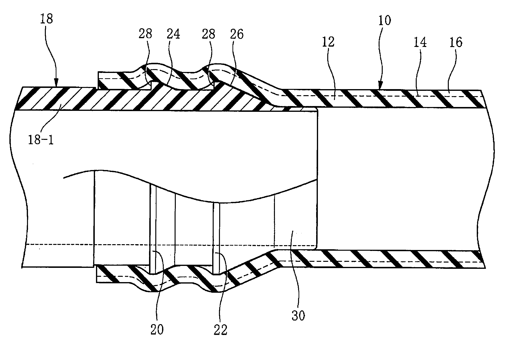
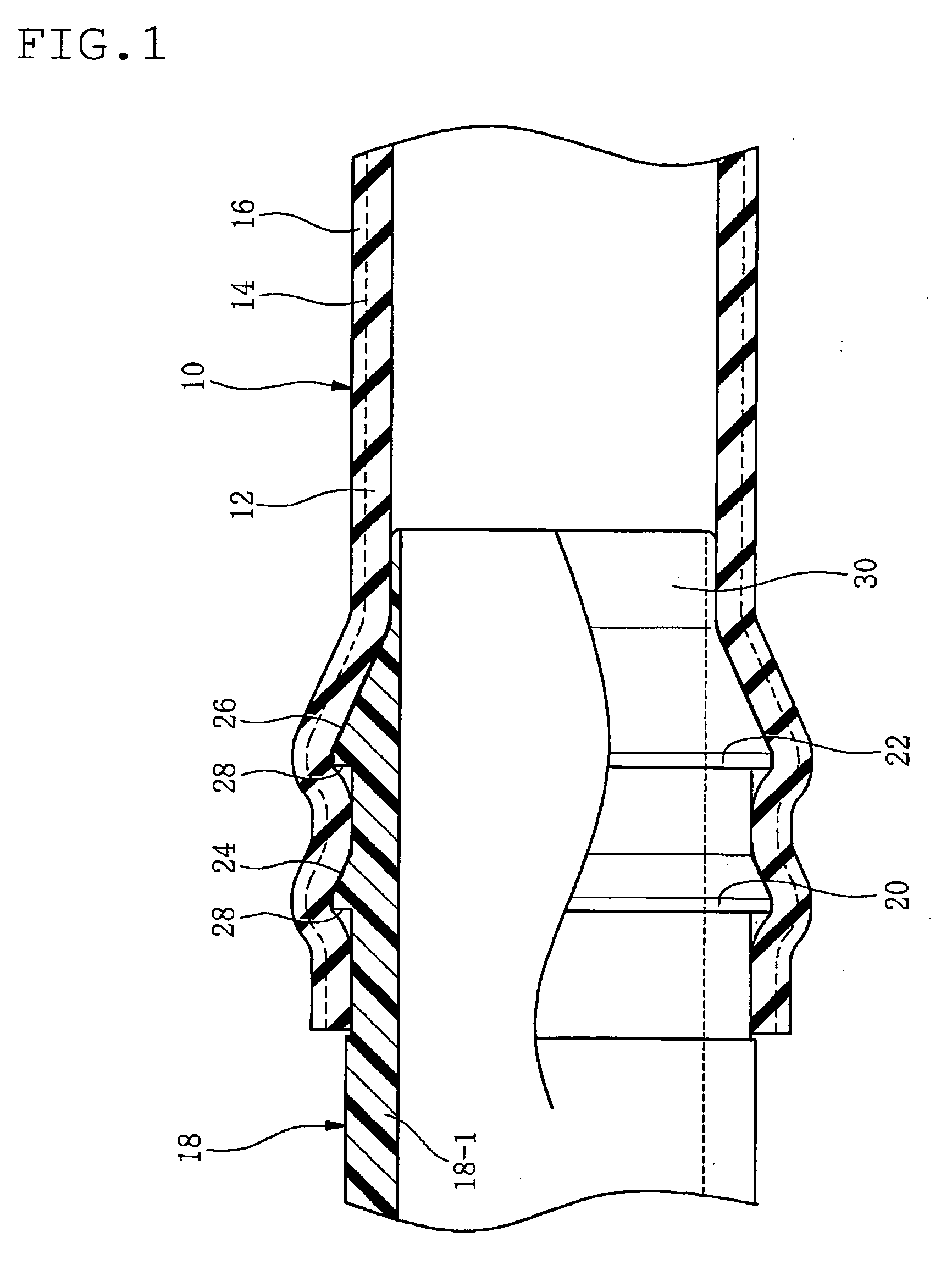
[0059] In FIG. 1, reference numeral 10 is a rubber hose (here, a radiator hose) having a multilayered construction including an inner surface rubber layer 12, a fiber reinforcing layer 14 and an outer surface rubber layer 16.

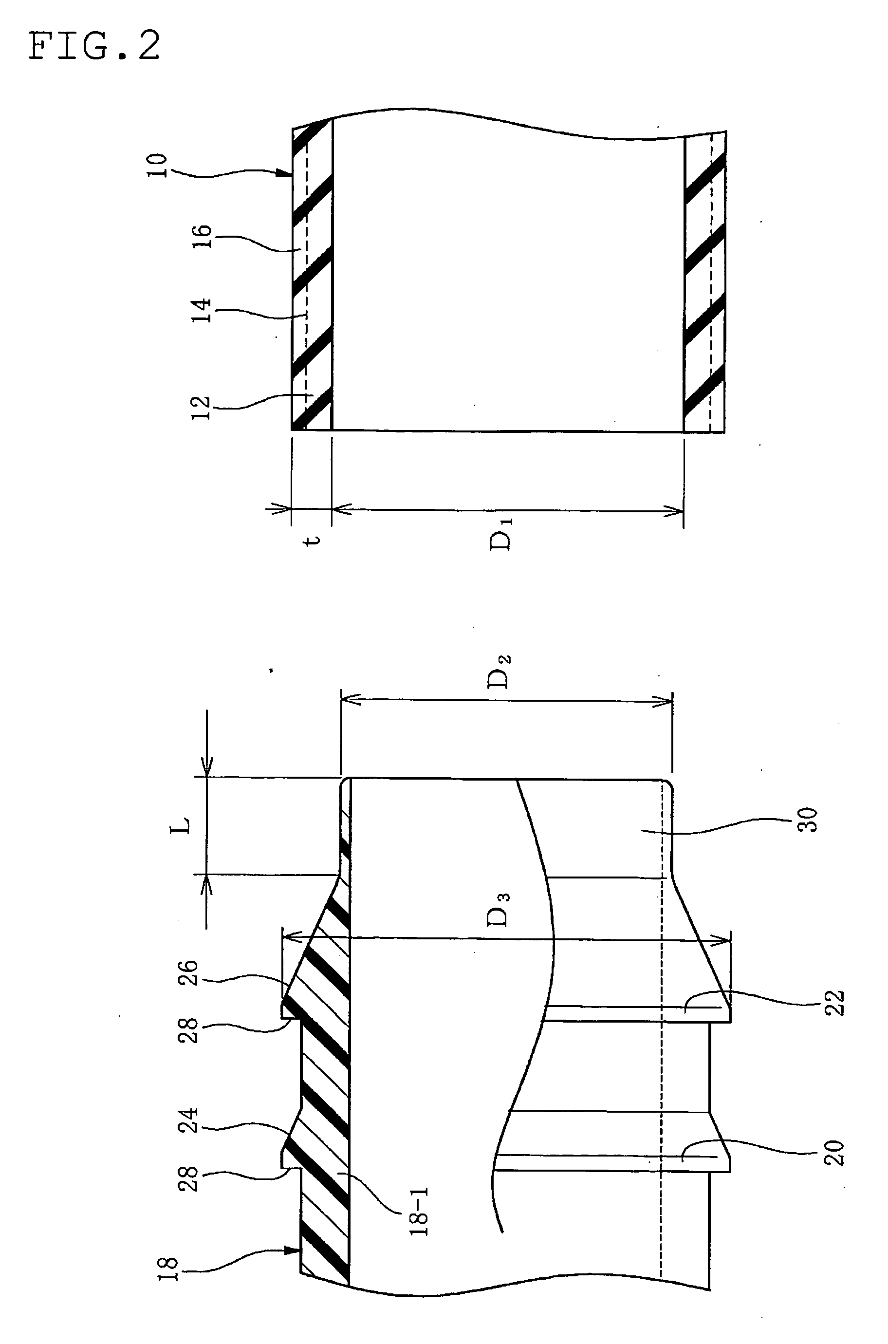
[0060] Reference numerals 18, 18-1 indicate a rigid connecting pipe, a rigid pipe body (here, made of resin, but may be made of metal). The connecting pipe 18 serves as a joint member for a piping. The connecting pipe 18 is provided with a plurality of annular ribs (here, two annular ribs) 20, 22 along an axial direction of the connecting pipe 18 or the pipe body 18-1. Each of the annular ribs 20, 22 has a generally saw-edged cross-section and is formed in an acute angled shape.

[0061] The annular ribs 20, 22 are portions to serve as stoppers relative to the rubber hose 10 by biting in an inner surface of the rubber hose 10 after the connecting pipe 18 is press-fitted in the rubber hose 10.

[0062] In this embodiment, one annular rib 22 is provided on a leading ...


PUM

PropertyMeasurementUnit
Lengthaaaaaaaaaa
Diameteraaaaaaaaaa
Lengthaaaaaaaaaa

Abstract

A rigid connecting pipe to be securely fixed in a rubber hose by press-fitting has a pipe body and an annular rib on a leading end portion of the pipe body. The annular rib has a generally saw-edged cross-section and is formed in an acute angled shape. The annular rib serves as a stopper relative to the rubber hose by biting in an inner surface of the rubber hose. The connecting pipe further has a tubular support portion on a leading end thereof beyond the annular rib. The support portion supports the rubber hose from an inner surface side thereof, on a leading end beyond the annular rib while being press-fitted in the rubber hose.

Description

BACKGROUND OF THE INVENTION [0001] 1. Field of the Invention [0002] The present invention relates to a rigid connecting pipe to be securely fixed to a rubber hose by means of press-fitting. [0003] 2. Description of the Related Art [0004] Previously, a resin hose or a rubber hose is used for transporting various fluids. [0005] In case of the latter rubber hose, a fixing structure of a connecting pipe to the rubber hose as shown in FIG. 6 has been typically used for a piping. [0006] In this fixing structure, a rigid connecting pipe 204 is formed with a bulge portion 202. The connecting pipe 204 is press-fitted or force-fitted in the rubber hose 200, a hose end portion 200A is fastened by a hose clamp 206 on an outer peripheral surface thereof on the connecting pipe 204, and thereby the rubber hose 200 is fixed to the connecting pipe 204 to provide a stop relative to the connecting pipe 204. [0007] However, this fixing structure entails a problem that the hose clamp 206 is required as ...

Claims


Application Information

Patent Timeline
IPC IPC(8): F16L33/00
CPCF16L33/30
Inventor MIYAJIMA, ATSUOSHIMIZU, KOJI
Owner TOKAI RUBBER IND LTD
Why Eureka
Try Eureka