Apparatus for Boundary Layer Air Inlet Utilization

a technology of air inlet and apparatus, applied in the direction of power plant cooling arrangement/mounting, aircraft power plant, power plant cooling arrangment, etc., can solve the problems of engine surge, loss of pressure recovery, loss of power and reduce aircraft performance, etc., to improve the utilization of boundary layer air and reduce drag

Active Publication Date: 2020-01-23
TEXTRON INNOVATIONS
View PDF6 Cites 0 Cited by
  • Summary
  • Abstract
  • Description
  • Claims
  • Application Information

AI Technical Summary

Benefits of technology

[0010]In other aspects the second air inlet is recessed within the predetermined offset space between the first air inlet and the fuselage, to improve the utilization of the boundary layer

Problems solved by technology

This turbulence can result in a loss of pressure recovery at the engine inlet face, and a loss of power and reduced aircraft performance.
The turbulent boundary air can also distort or disrupt the air flow at the engine inlet face, leading to engine surges.
This remedy does not utilize the boundary layer air (it is simply bypassed around the engine inlet) and has the disadvantage of increased drag because the engine air inlet extends away from the aircraft surface.
Moreover, the increase in velocity also worsens the problems of pressure recovery and disruption of the air flow.
However, when the aircraft is on the ground air flow en

Method used


Image

  • Apparatus for Boundary Layer Air Inlet Utilization
  • Apparatus for Boundary Layer Air Inlet Utilization
  • Apparatus for Boundary Layer Air Inlet Utilization

Examples


Embodiment Construction

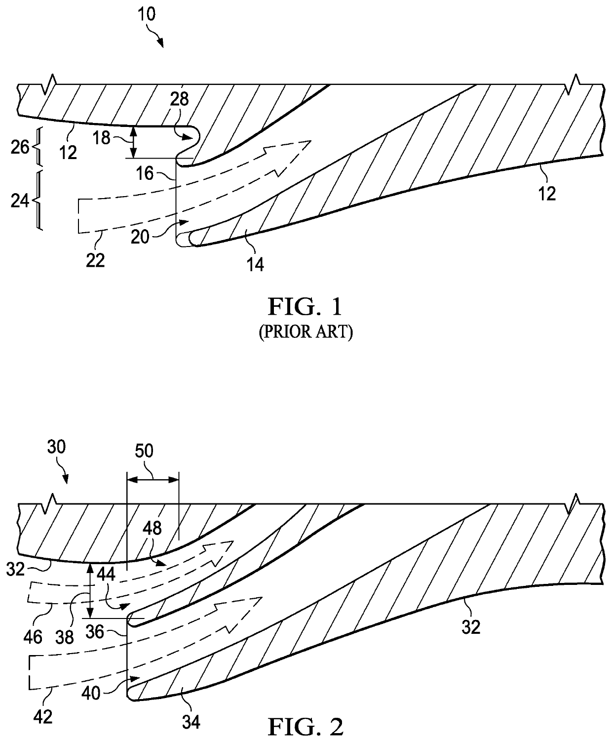
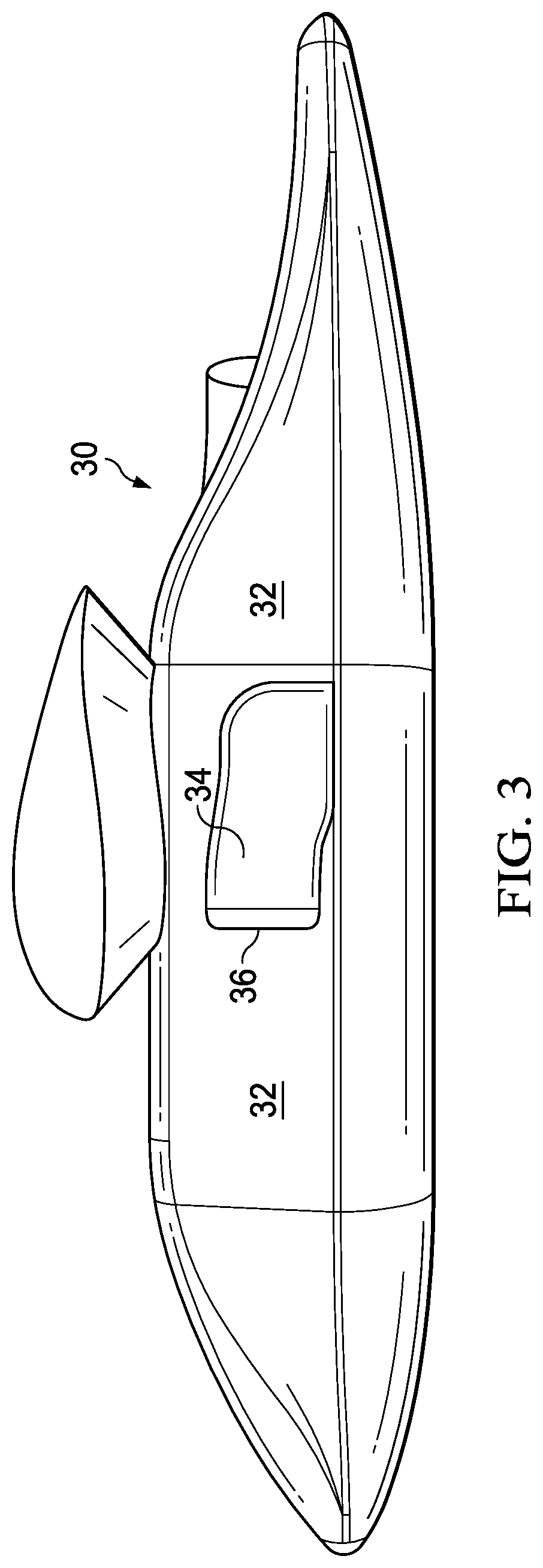
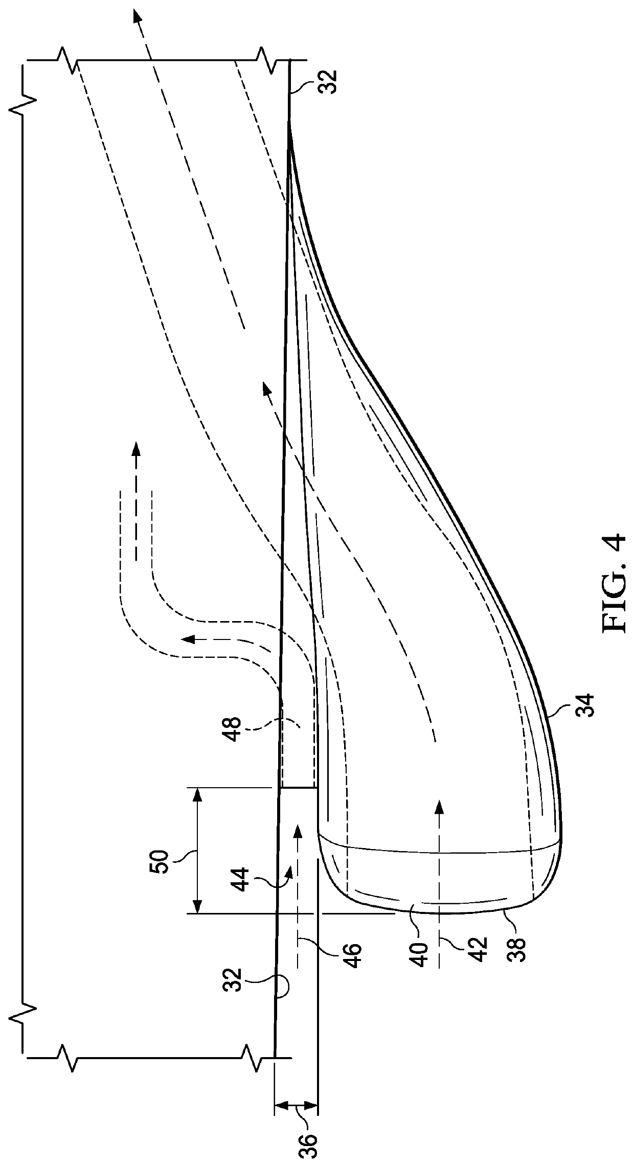
[0016]In an advance in the state of the art, a novel air inlet apparatus for ram air engines as used in high speed aircraft such as rotorcraft is provided that improves engine performance and reduces drag by diverting the boundary layer air into the engine hay for cooling the engine bay without adding structures that protrude into the airstream along the rotorcraft. The structure for diverting the boundary layer air is incorporated into an existing structural feature of the rotorcraft, the offset spacing of the engine's ram air inlet. The primary inlet (ram air) airstream, cleansed of most of the boundary layer component routed into this secondary air inlet disposed within the offset space, is undisrupted air—unimpeded by turbulence, distortion, or erratic flow (surges) into the engine for maximum engine performance.

[0017]FIG. 1 illustrates a cross section view of a ram air inlet for airflow to an engine of an aircraft or rotorcraft according to the prior art. In this example of as ...


PUM


Abstract

A boundary layer utilization apparatus for intake of air to a high speed aircraft, comprises a first air inlet adjacent an exterior surface of a fuselage of the aircraft and offset from the fuselage enough to integrate a second air inlet in the offset space to ingest and divert the boundary layer air flowing next to the fuselage into the aircraft for a useful purpose such as cooling the engine compartment. The second air inlet is disposed aft of the first air inlet to minimize hot gas re-ingestion.

Description

BACKGROUND OF THE INVENTION1. Field of the Invention[0001]The present invention generally concerns the field of aircraft boundary layer air management and more specifically concerns apparatus for utilizing boundary layer air flowing along the fuselage of an aircraft to provide air for cooling applications within the aircraft.2. Background of the Invention and Disclosure of Prior Art[0002]In a high speed aircraft, a ram air engine inlet may be typically disposed proximate but slightly away from the surface of the fuselage to prevent the ingestion of turbulent boundary layer air flowing along the exterior surface of the moving aircraft. This turbulence can result in a loss of pressure recovery at the engine inlet face, and a loss of power and reduced aircraft performance. The turbulent boundary air can also distort or disrupt the air flow at the engine inlet face, leading to engine surges. A conventional remedy is to shift the engine air inlet away from the exterior surface of the air...

Claims


Application Information

Patent Timeline
IPC IPC(8): B64D33/08B64D33/02F15D1/00
CPCB64D33/08F15D1/0025B64D2033/0253B64D33/02
Inventor PARSONS, THOMAS DEWEYROSADO, ANGEL DAVIDREYNOLDS, ROBERT PAULHAYNES, DAVID FRANKGONS, WILLIAM MATHISEN
Owner TEXTRON INNOVATIONS
Why Eureka
Try Eureka