Radio frequency energy-harvesting apparatus

a technology of energy harvesting apparatus and radio frequency, which is applied in the direction of reradiation, measurement devices, instruments, etc., can solve the problems of low conversion efficiency of the related art radio frequency energy harvesting apparatus and incongruity of indicator components with higher power consumption, so as to save energy and save energy

Active Publication Date: 2020-02-20
DELTA ELECTRONICS INC +1
View PDF0 Cites 3 Cited by
  • Summary
  • Abstract
  • Description
  • Claims
  • Application Information

AI Technical Summary

Benefits of technology

[0028]1. The radar wave beam of the radar wave transmitted from the radio frequency energy-transmitting apparatus is directed toward the location of the radio frequency energy-harvesting apparatus, so that the energy density of the location of the radio frequency energy-harvesting apparatus is higher, so that the radio frequency energy-harvesting apparatus obtains higher energy.
[0029]2. According to the concept of the radar reflection harmonic wave, the radio frequency energy-transmitting apparatus can detect the location of the radio frequency energy-harvesting apparatus easily, so that the circuit structure of the radio frequency energy-harvesting apparatus is simple and energy is saved to accord with the concept of the energy-harvesting apparatus. The present invention does not need the GPS, Beacon or Wi-Fi communication components to locate the radio frequency energy-harvesting apparatus.

Problems solved by technology

1. The wireless signals transmitted by most of the related art radio frequency energy-transmitting apparatuses (for examples, the radio or telecom base station) is ominidirectional, so that the energy density at the location of the related art radio frequency energy-harvesting apparatus is possibly not high enough, so that the conversion efficiency of the related art radio frequency energy-harvesting apparatus is low.
2. The wireless signal transmitted by some of the related art radio frequency energy-transmitting apparatuses is directional to the location of the related art radio frequency energy-harvesting apparatus, but the location indicator component with higher power consumption has to be arranged in the related art radio frequency energy-harvesting apparatus. For example, locating the related art radio frequency energy-harvesting apparatus can be achieved by the GPS, Beacon or Wi-Fi communication components. However, the location indicator component with higher power consumption does not accord with the spirit of the energy-harvesting apparatus.

Method used


Image

  • Radio frequency energy-harvesting apparatus
  • Radio frequency energy-harvesting apparatus
  • Radio frequency energy-harvesting apparatus

Examples


Embodiment Construction

[0034]Please refer to following detailed description and figures for the technical content of the present invention. The following detailed description and figures are referred for the present invention, but the present invention is not limited to it.

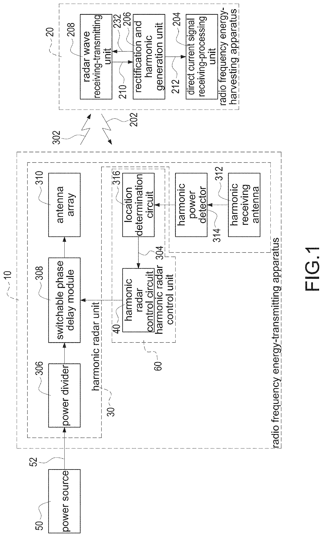
[0035]FIG. 1 shows a block diagram of the radio frequency energy-transmitting apparatus and the radio frequency energy-harvesting apparatus of the present invention. A radio frequency energy-transmitting apparatus 10 with a location detection function is applied to a radio frequency energy-harvesting apparatus 20 and a power source 50. The radio frequency energy-transmitting apparatus 10 comprises a harmonic radar unit 30 and a harmonic radar control unit 60. The harmonic radar unit 30 comprises a power divider 306, a switchable phase delay module 308, an antenna array 310, a harmonic receiving antenna 312 and a harmonic power detector 314. The harmonic radar control unit 60 comprises a harmonic radar control circuit 40 and a location d...


PUM


Abstract

A radio frequency energy-harvesting apparatus is applied to a radio frequency energy-transmitting apparatus with a location detection function. The radio frequency energy-harvesting apparatus includes a direct current signal receiving-processing unit, a rectification and harmonic generation unit, and a radar wave receiving-transmitting unit. The rectification and harmonic generation unit is electrically connected to the direct current signal receiving-processing unit. The radar wave receiving-transmitting unit is electrically connected to the rectification and harmonic generation unit. The radio frequency energy-transmitting apparatus transmits a radar wave scanning to a space; after the radar wave receiving-transmitting unit receives the radar wave, according to the radar wave, the radar wave receiving-transmitting unit generates an alternating current signal; the radar wave receiving-transmitting unit transmits the alternating current signal to the rectification and harmonic generation unit; the rectification and harmonic generation unit generates a radar reflection harmonic wave and a direct current signal.

Description

CROSS-REFERENCE TO RELATED APPLICATION[0001]This application is a divisional application of U.S. patent application Ser. No. 14 / 955,301 filed on Dec. 1, 2015 and entitled “ RADIO FREQUENCY ENERGY-TRANSMITTING APPARATUS WITH LOCATION DETECTION FUNCTION AND RADIO FREQUENCY ENERGY-HARVESTING APPARATUS AND RADIO FREQUENCY ENERGY-TRANSMITTING METHOD WITH LOCATION DETECTION FUNCTION.”, which claims priority to TW104133681 filed Oct. 14, 2015. The entire disclosures of the above applications are all incorporated herein by reference.BACKGROUND OF THE INVENTIONField of the Invention[0002]The present invention relates to an energy-transmitting apparatus, an energy-harvesting apparatus and an energy-transmitting method, and especially relates to a radio frequency energy-transmitting apparatus with a location detection function, a radio frequency energy-harvesting apparatus and a radio frequency energy-transmitting method with the location detection function.Description of the Related Art[0003]...

Claims


Application Information

Patent Timeline
Patent Type & Authority Applications(United States)
IPC IPC(8): H02J50/20G01S13/75
CPCH02J50/20G01S13/75H02J50/001
Inventor HUANG, TZUEN-HSIYANG, SHENG-FANCHEN, CHUN-CHENGCHUNG, PEI-JUNGLU, CHUN-YI
Owner DELTA ELECTRONICS INC
Why Eureka
Try Eureka