Electrical connector and connector device

Active Publication Date: 2020-07-02
DAIICHI SEIKO CO LTD
View PDF0 Cites 0 Cited by
  • Summary
  • Abstract
  • Description
  • Claims
  • Application Information

AI Technical Summary

Problems solved by technology

In an electronic instrument where such a type of connector device is used therein, electromagnetic interference that is caused by radiation of an electromagnetic wave or the like may be problematic, so that a shield function may be provided to a connector device.

Method used


Image

  • Electrical connector and connector device
  • Electrical connector and connector device
  • Electrical connector and connector device

Examples


Embodiment Construction

)

[0023]Hereinafter, an embodiment(s) of an electrical connector and a connector device as disclosed in the present application will be explained in detail, with reference to the accompanying drawing(s). Additionally, this invention is not limited by an embodiment(s) as illustrated below.

[0024]1. Configuration of Connector Device

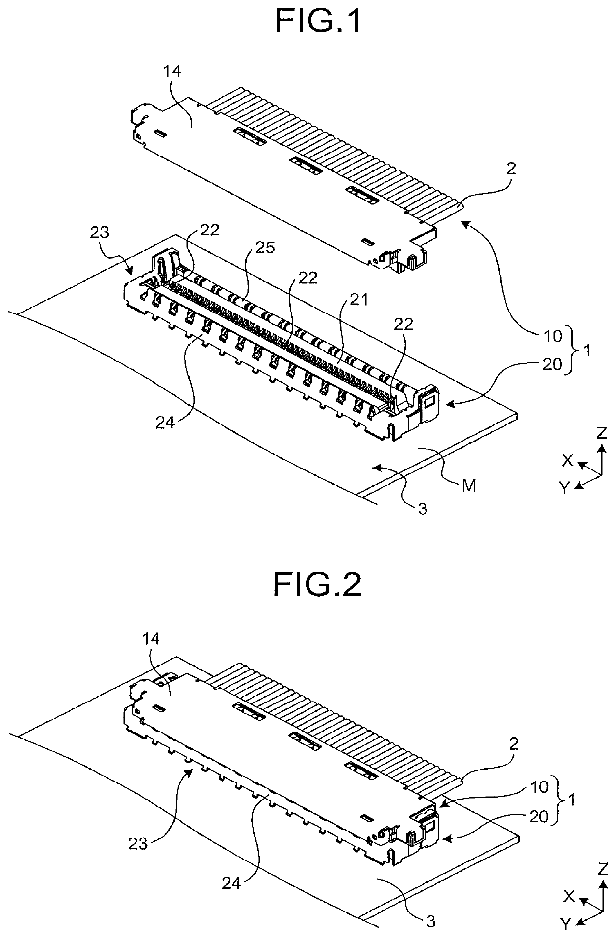
[0025]First, a connector device that includes a plug connector and a receptacle connector according to an embodiment will be explained with reference to FIG. 1 and FIG. 2.

[0026]As illustrated in FIG. 1, a connector device 1 according to an embodiment includes a plug connector 10 that is connected to terminals of a plurality of coaxial cables 2 and a receptacle connector 20 that is attached to a wiring substrate 3. The plurality of coaxial cables 2 are an example of a signal transmission medium.

[0027]Additionally, the plug connector 10 may be a configuration to be connected to a terminal of a signal transmission medium such as a flexible printed circuit (FPC) ...


PUM


Abstract

An electrical connector is attached to a wiring substrate and mated with a counterpart connector connected to a signal transmission medium. A shell of the electrical connector has a pair of wall parts that contact a ground member on the counterpart connector. One wall part distant from the signal transmission medium includes a first side plate that has one end attached to a ground conductive path of the wiring substrate and extends in a direction away from the wiring substrate, a joining part that has one end joined to another end of the first side plate, and a second side plate that has one end joined to another end of the joining part and extends in a direction closer to the wiring substrate. The second side plate has a contact piece that extends in a direction away from the wiring substrate and elastically contacts the ground member.

Description

CROSS-REFERENCE TO RELATED APPLICATION(S)[0001]This application is based upon and claims the benefit of priority to Japanese Patent Application No. 2018-248235 filed on Dec. 28, 2018, the entire contents of which are herein incorporated by reference.BACKGROUND OF THE INVENTION1. Field of the Invention[0002]A disclosed embodiment relates to an electrical connector and a connector device.2. Description of the Related Art[0003]Conventionally, a connector device for electrically connecting a signal transmission medium such as a coaxial cable, a flexible printed circuit (FPC), or a flexible flat cable (FFC) to a wiring substrate has been widely used in an electronic instrument. Such a connector device includes a first connector that is connected to a terminal of a signal transmission medium and a second connector that is connected to a wiring substrate. In an electronic instrument where such a type of connector device is used therein, electromagnetic interference that is caused by radiat...

Claims


Application Information

Patent Timeline
Patent Type & Authority Applications(United States)
IPC IPC(8): H01R13/6581H01R12/79
CPCH01R13/6581H01R12/79H01R13/652H01R13/6594H01R13/6582
Inventor MASUNAGA, TAKASHI
Owner DAIICHI SEIKO CO LTD
Why Eureka
Try Eureka