Connector and outer conductor

a technology of connecting conductor and connecting part, which is applied in the direction of coupling contact member, coupling device connection, electrical apparatus, etc., can solve the problems of unavoidable tiny clearance in the connected part of the shield case, and unavoidable tiny clearance in the seam, so as to improve the shielding function

Active Publication Date: 2021-10-14
AUTONETWORKS TECH LTD +2
View PDF0 Cites 1 Cited by
  • Summary
  • Abstract
  • Description
  • Claims
  • Application Information

AI Technical Summary

Benefits of technology

[0008]According to the first and second aspects of the disclosure, a shielding function can be improved.

Problems solved by technology

In the above conventional shield connector, it is unavoidable that a tiny clearance is formed in a connected part of the shield case and the shield cover.
Since this tubular portion is formed by bending the metal plate material and splicing the metal plate material into a rectangular tube, it is unavoidable that a tiny clearance is formed in a seam.

Method used


Image

  • Connector and outer conductor
  • Connector and outer conductor
  • Connector and outer conductor

Examples


first embodiment

[0031]Hereinafter, a first specific embodiment of the present disclosure is described with reference to FIGS. 1 to 12. Note that the present invention is not limited to these illustrations and is intended to be represented by claims and include all changes in the scope of claims and in the meaning and scope of equivalents.

[0032]In the following description, a right side in FIGS. 1, 3 and 6 and an oblique right-lower side in FIGS. 2 and 5 to 7 is defined as a front side concerning a front-rear direction. Upper and lower sides shown in FIGS. 1 to 13 are directly defined as upper and lower sides concerning a vertical direction. Left and right sides shown in FIG. 8 are directly defined as left and right sides concerning a lateral direction.

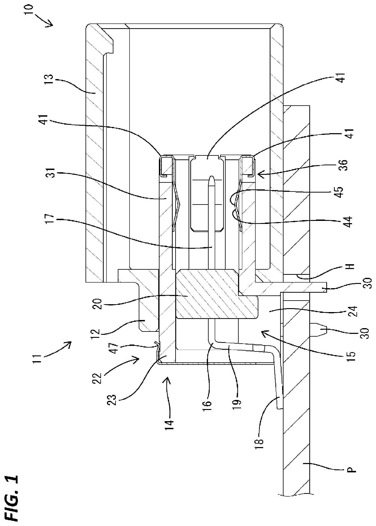
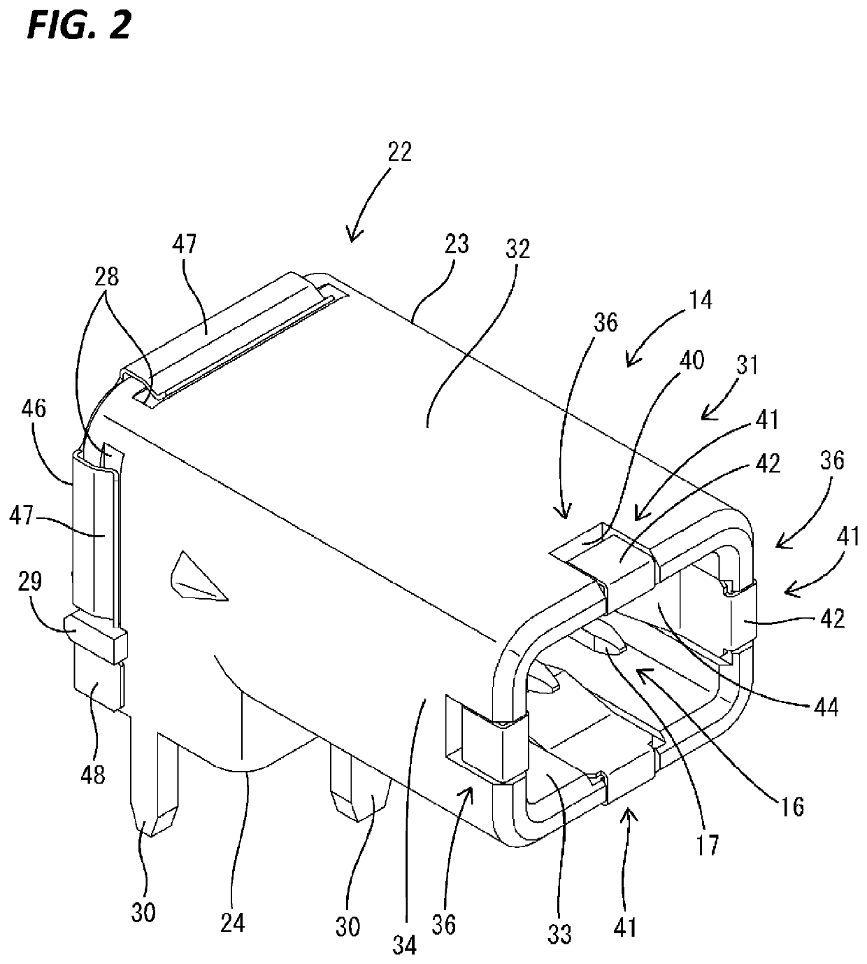
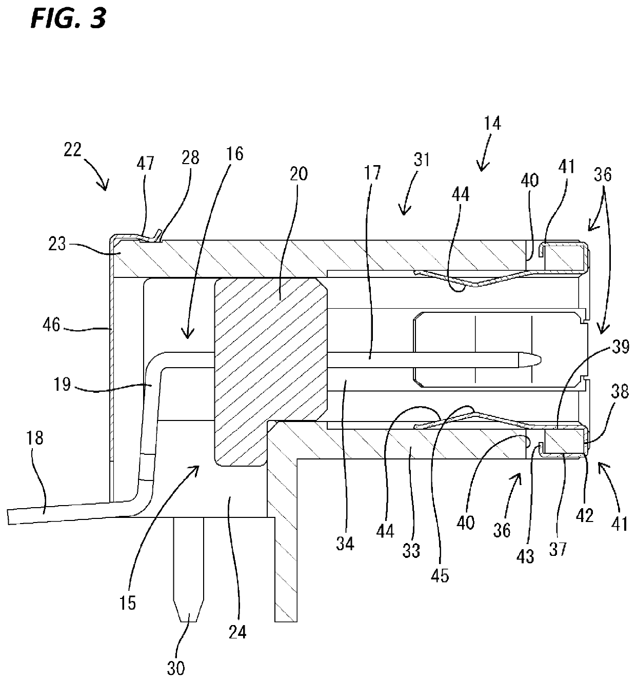
[0033]A male shield connector 10 (connector as claimed) of the first embodiment includes, as shown in FIG. 1, a male housing 11 and a male shield terminal 14 accommodated in the male housing 11. The male housing 11 is a single member made of synthetic...

second embodiment

[0066]Next, a second specific embodiment of the present disclosure is described with reference to FIGS. 13 to 15. The board connecting portions 18 of the male inner conductors 16 of the male shield connector 10 of the above first embodiment are surface-mounted on the circuit board P, whereas board connecting portions 72 of male inner conductors 71 (inner conductor as claimed) of a male shield connector 70 (connector as claimed) of the second embodiment are passed through through holes T of a circuit board P and fixed by soldering (not shown). Since the other configuration is the same as in the above first embodiment, the same components are denoted by the same reference signs and structures, functions and effects thereof are not described.

Other Embodiments

[0067]The present invention is not limited to the above described and illustrated embodiments. For example, the following embodiments are also included in the technical scope of the present invention.

[0068]Although the tubular port...


PUM


Abstract

It is aimed to improve a shielding function. A male shield connector (10) is provided with male inner conductors (16), a male dielectric (20) and a male outer conductor (22). The male outer conductor (22) includes a tubular portion (31) to which a female outer conductor (62) of a female connector (50) is connected, and the tubular portion (31) includes no boundary dividing the tubular portion (31) in a circumferential direction. Since the tubular portion (31) is so formed that a coupling part such as a seam or a dividing boundary such as a slit is not present, the male shield connector (10) is excellent in shielding performance.

Description

TECHNICAL FIELD[0001]The present invention relates to a connector and an outer conductor.BACKGROUND[0002]Patent Document 1 discloses, as a shield connector to be applied to a communication cable, a connector configured such that an inner conductor (inner conductor terminal) is accommodated in a dielectric (inner housing) and the dielectric is surrounded by an outer conductor (shield shell). The outer conductor is configured into a tubular shape by uniting a shield case and a shield cover formed by bending metal plate materials.PRIOR ART DOCUMENTPatent Document[0003]Patent Document 1: JP 2012-195315ASUMMARY OF THE INVENTIONProblems to be Solved[0004]In the above conventional shield connector, it is unavoidable that a tiny clearance is formed in a connected part of the shield case and the shield cover. Further, the shield case includes a tubular portion. Since this tubular portion is formed by bending the metal plate material and splicing the metal plate material into a rectangular tu...

Claims


Application Information

Patent Timeline
Patent Type & Authority Applications(United States)
IPC IPC(8): H01R13/6582H01R13/502H01R13/05
CPCH01R13/6582H01R13/05H01R13/502H01R12/724
Inventor MAESOBA, HIROYOSHIICHIO, TOSHIFUMI
Owner AUTONETWORKS TECH LTD
Why Eureka
Try Eureka