Magnetic disk device with improved shielding

a magnetic disk and shielding function technology, applied in the field of magnetic disk devices, can solve the problems of increased external size by the size of the shielding member, increased cost, and difficulty in exhibiting the shielding function to a sufficient degree, and achieve the effect of improving the shielding function of the magnetic head

Inactive Publication Date: 2006-03-16
WESTERN DIGITAL TECH INC
View PDF21 Cites 1 Cited by
  • Summary
  • Abstract
  • Description
  • Claims
  • Application Information

AI Technical Summary

Benefits of technology

[0013] It is a feature of the present invention to provide a magnetic disk device capable of improving the shielding function for the magnetic head yet maintaining a form factor relying upon an inexpensive constitution.

Problems solved by technology

According to the prior art 1, however, the shielding member is provided on the outside of the housing separated away from the magnetic head and, hence, the shielding function is not fully exhibited and, further, the external size increases by the size of the shielding member.
According to the prior art 2, the shielding member is provided on only the base portion and the cover portion corresponding to the magnetic head, making it difficult to exhibit the shielding function to a sufficient degree.
Therefore, it becomes necessary to provide a housing of a particular shape and to impart the function of a housing to the shielding member, arising the problem of increased cost.
Moreover, the prior arts 1 to 4 are not capable of exhibiting the shielding function to a sufficient degree against the external magnetic field which is in the transverse direction of the magnetic head (from the direction of the side surfaces).

Method used


Image

  • Magnetic disk device with improved shielding
  • Magnetic disk device with improved shielding
  • Magnetic disk device with improved shielding

Examples


first embodiment

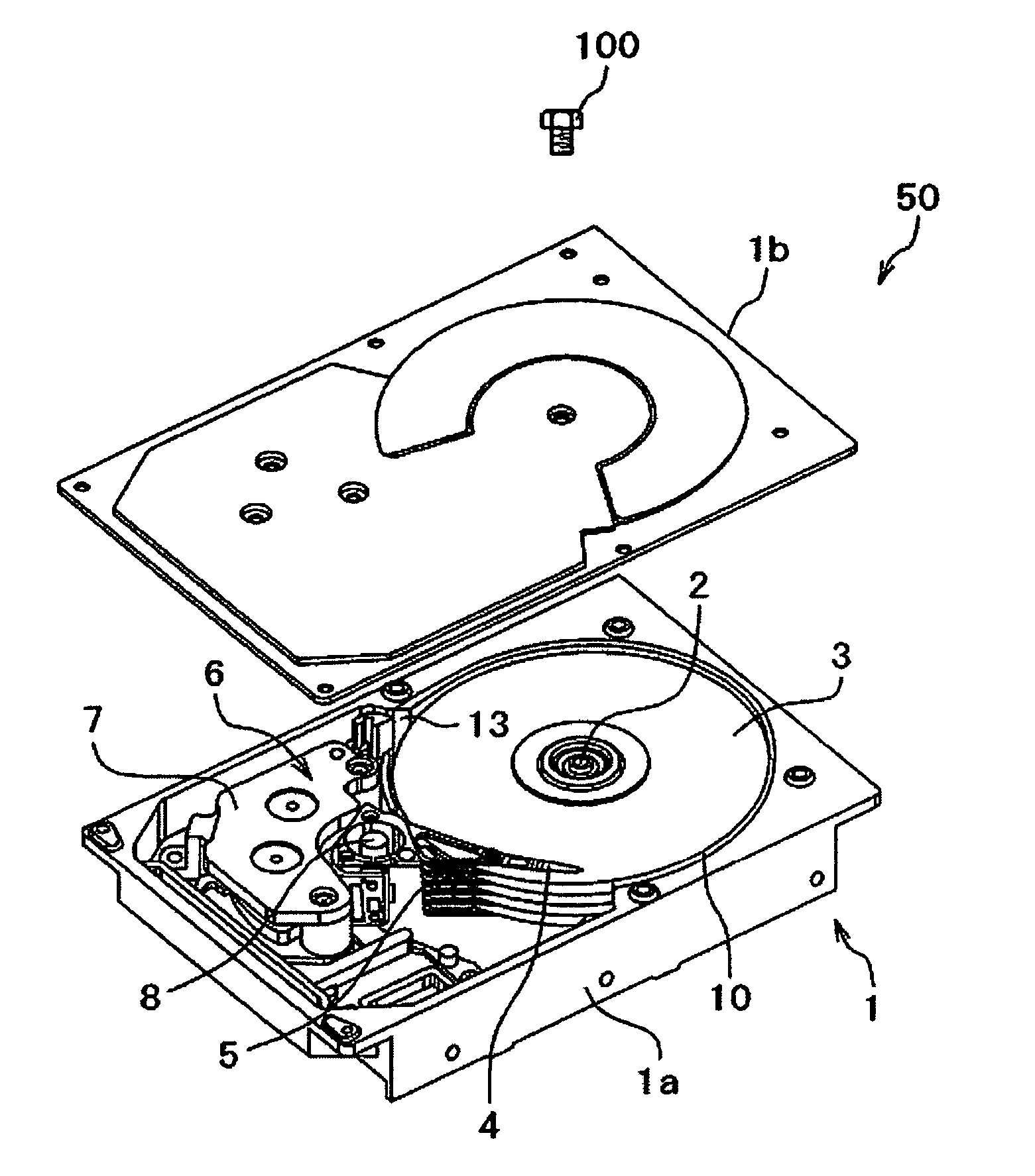
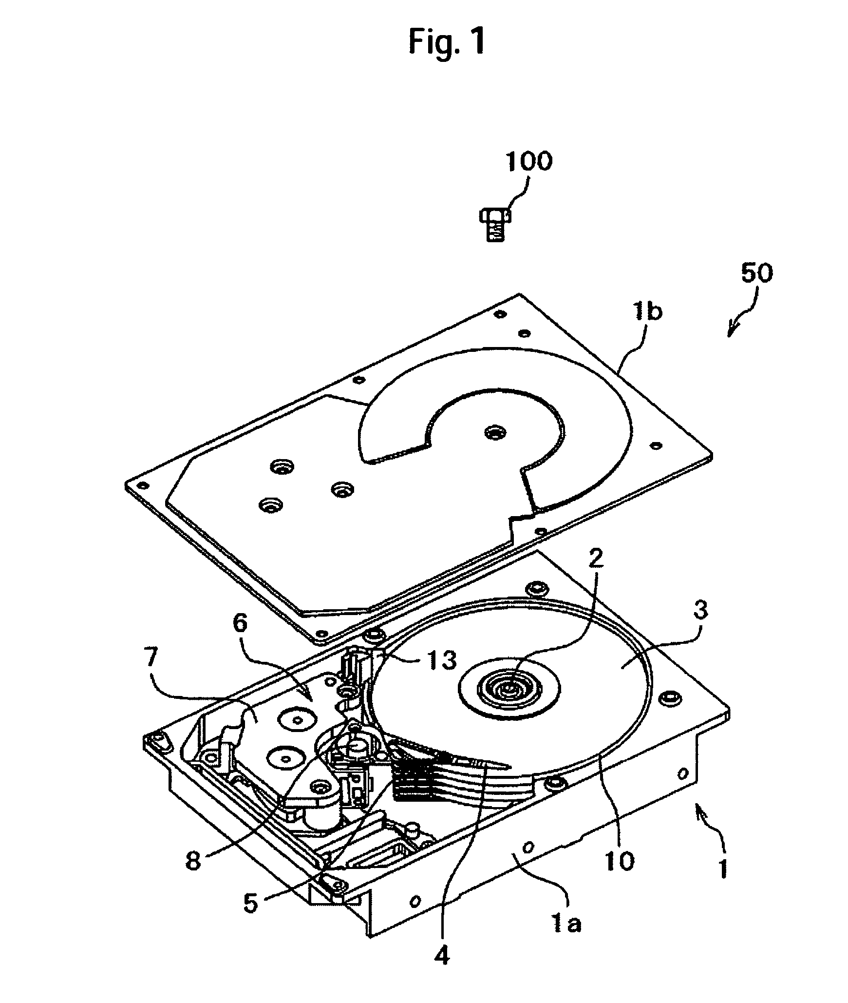
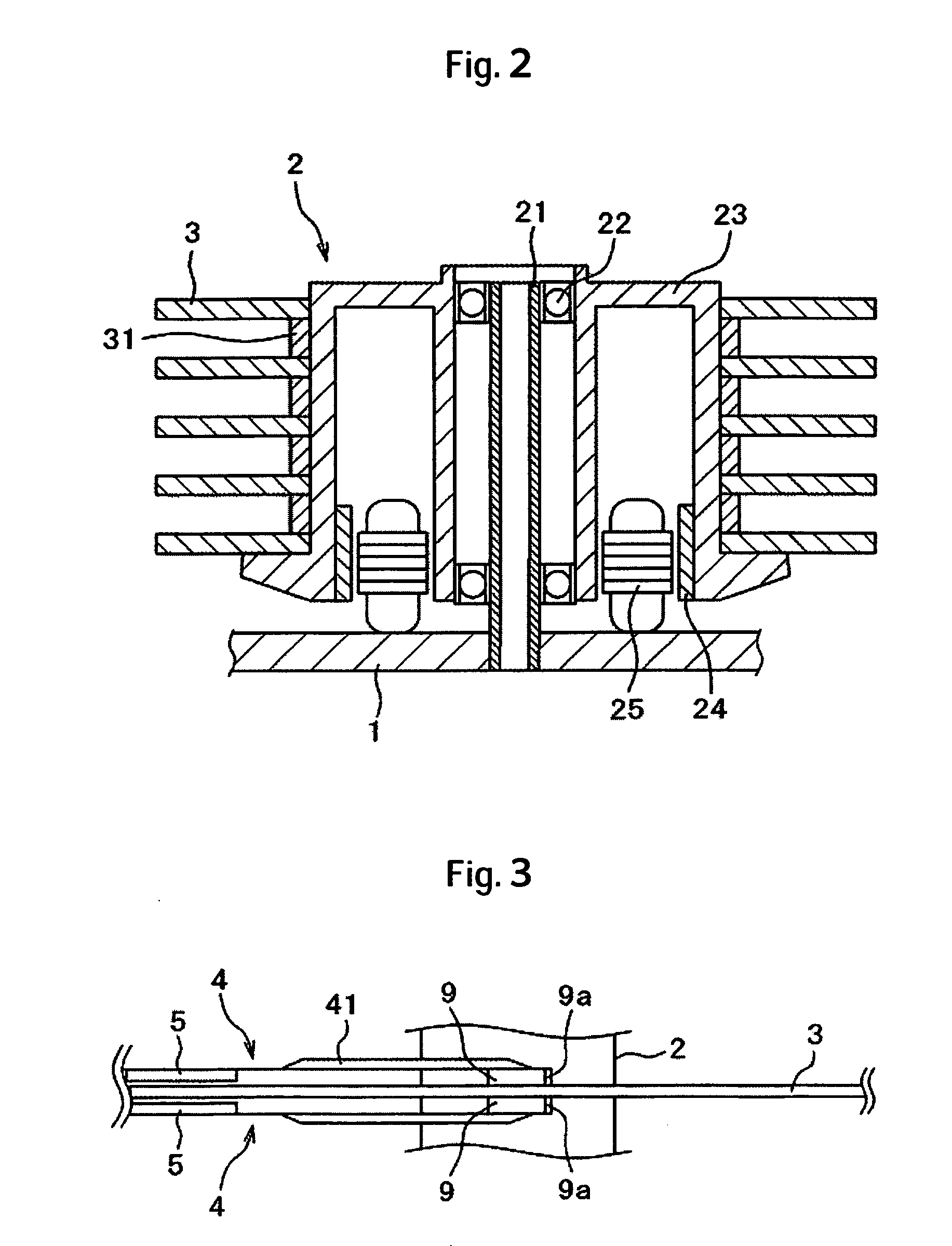
[0044] A magnetic disk device of the invention will now be described with reference to FIGS. 1 to 12. The whole constitution of the magnetic disk device 50 of the embodiment will now be described with reference to FIGS. 1 to 4. FIG. 1 is a perspective view of the magnetic disk device 50 of this embodiment, FIG. 2 is a vertical sectional view of a spindle mechanism unit of FIG. 1, FIG. 3 is a side view of a magnetic head slider unit of FIG. 1, and FIG. 4 is a perspective view of a shroud of FIG. 1 in the state of a single unit thereof.

[0045] The magnetic disk device 50 accommodates a spindle mechanism 2, a magnetic disk 3, a magnetic head support mechanism 4, a positioning mechanism 6 and a shroud 10 inside a housing 1.

[0046] The housing 1 is constituted by a base 1a of the shape of a lunch box and a cover 1b covering the opening in the upper surface of the base 1a, and is of a structure which is split into upper and lower halves. The base 1a is of a structure same as the housing of...

third embodiment

[0070] In the third embodiment, the cover 1b is constituted by using a nonmagnetic material, and an upper shield 91 made of a magnetic material and having nearly the same size as the outer diameter of the shroud 10 is provided on the inside of the cover 1b (on the side of the disk surface). The upper shield 91 constitutes a portion of the cover 1b. Further, the upper shield 91 is not in contact with the spindle mechanism 2. The outer circumferential portion 92 of the upper shield 91 is in contact with the upper end 11 of the shroud 10 in a state where the cover 1b is mounted on the base 1a. Therefore, there is no need of forming the cover 1b by using the magnetic material, and a conventional cover of a nonmagnetic material can be used. Further, being provided on the inside of the cover 1b, the form factor of the device can be maintained. Moreover, since the cover 1b and the spindle mechanism 2 are not in contact, the embodiment can be applied even to a cantilevered spindle structure...


PUM

PropertyMeasurementUnit
thicknessaaaaaaaaaa
thicknessaaaaaaaaaa
thicknessaaaaaaaaaa

Abstract

Embodiments of the invention provide a magnetic disk device which improves the shielding function for the magnetic heads yet maintaining a form factor relying upon an inexpensive constitution. In one embodiment, a magnetic disk device comprises a rotary disk-type magnetic disk; a magnetic head for recording or reproducing information; a magnetic head support mechanism for supporting the magnetic head; a shroud having an opening in which the magnetic head support mechanism is inserted, and surrounding the outer circumference of the magnetic disk; and a housing. The housing includes a base and a cover, and accommodates the magnetic disk, the magnetic head, the magnetic head support mechanism and the shroud. The base is constituted by using a nonmagnetic material and the shroud is constituted by using a magnetic material.

Description

CROSS-REFERENCES TO RELATED APPLICATIONS [0001] This application claims priority from Japanese Patent Application No. JP 2004-263309, filed Sep. 10, 2004, the entire disclosure of which is incorporated herein by reference. BACKGROUND OF THE INVENTION [0002] This invention relates to a magnetic disk device and, particularly, to a magnetic disk device for recording information relying upon a vertical magnetic recording system. [0003] In a magnetic disk device employing the vertical magnetic recording system, when a magnetic field is applied from the outer side, the magnetic head works to concentrate the external magnetic field onto a main magnetic pole due to the constitution of the magnetic head often arising a problem in that the data recorded on a disk are destroyed. Since it is not possible to decrease the intensity of the external floating magnetic field itself acting on the magnetic disk device, it is necessary to provide the magnetic disk device with a function that exhibits sh...

Claims


Application Information

Patent Timeline
Patent Type & Authority Applications(United States)
IPC IPC(8): G11B17/00
CPCG11B33/1493
Inventor EGUCHI, TAKEHIKOKURITA, MASAYUKISHIMIZU, TOSHIHIKOTOKUYAMA, MIKIO
Owner WESTERN DIGITAL TECH INC
Why Eureka
Try Eureka