Piezoceramic Ultrasonic Transducer

a technology of ultrasonic transducers and ceramics, applied in the direction of mechanical vibration separation, printed circuit components, printed circuit assembling, etc., can solve the problems of pcp may start vibrating, mechanical vibratory decoupling quality is largely affected, and the mechanical decoupling between the oscillator and the pcb gets worse, so as to achieve the effect of not affecting performan

Pending Publication Date: 2021-04-29
CONTINENTAL AUTOMOTIVE GMBH
View PDF0 Cites 0 Cited by
  • Summary
  • Abstract
  • Description
  • Claims
  • Application Information

AI Technical Summary

Benefits of technology

[0005]An object of the present invention, therefore, is to provide a piezoceramic ultrasonic transducer for a vehicle, which is capable of operating in

Problems solved by technology

One problem with these elastomeric elements is, however, that the quality of mechanical vibratory decoupling largely depends on the temperatures in which the piezoceramic oscillator works.
If, for example, the temperature is very low, the elastomeric element may become hard and therefore the mechanical decoupling between the oscillator and the PCB gets worse.
As

Method used


Image

  • Piezoceramic Ultrasonic Transducer
  • Piezoceramic Ultrasonic Transducer
  • Piezoceramic Ultrasonic Transducer

Examples


Embodiment Construction

[0020]Within this disclosure, the same reference numbers refer to the same components.

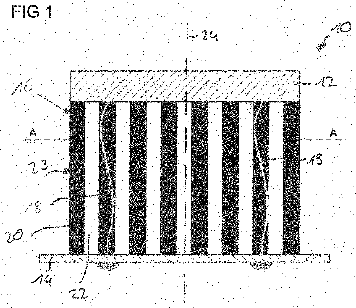
[0021]FIG. 1 shows a schematic view of a piezoceramic ultrasonic transducer 10 of a first embodiment of the present invention. The piezoceramic ultrasonic transducer 10 may be used for distance measurements, for example in air springs, but also for distance measuring systems in vehicles.

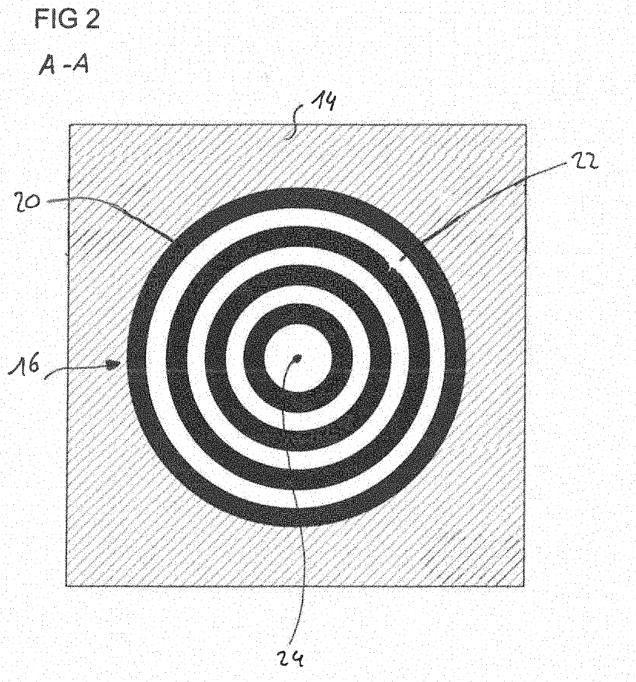
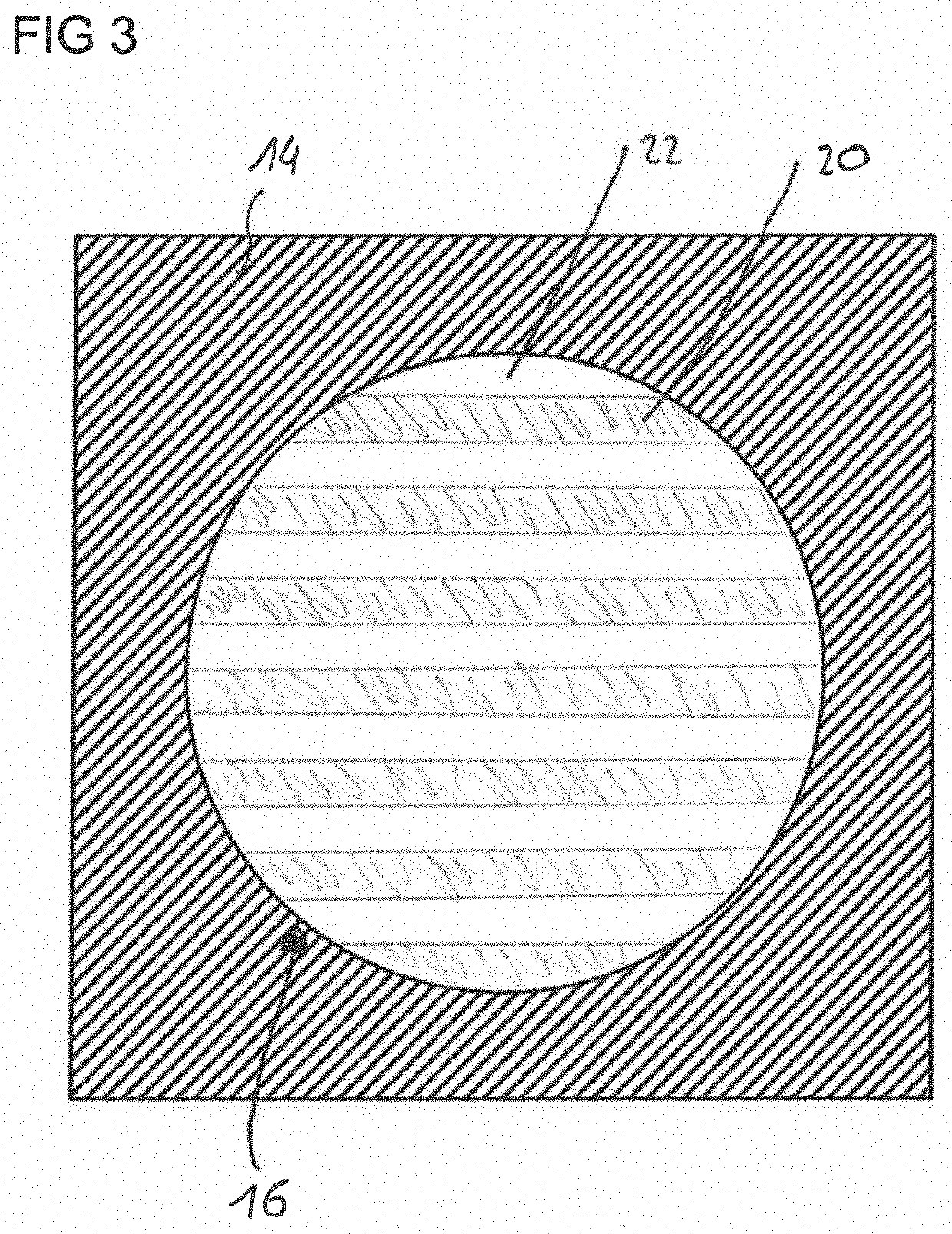
[0022]The piezoceramic ultrasonic transducer 10 includes a disc-shaped piezoceramic oscillator 12 for generating ultrasonic waves and a printed circuit board (PCB) 14 for providing electric power to the piezoceramic oscillator 12. The piezoceramic ultrasonic transducer 10 further includes a composite elastomeric element 16 which is arranged between the oscillator 12 and the PCB 14 for supporting the oscillator 12 on the PCB 14. Electrical connections 18 are provided within composite elastomeric element 16 for electrical connecting the oscillator 12 with the PCB 14. These electrical connections 18 may be, for example...


PUM


Abstract

A piezoceramic ultrasonic transducer for a vehicle includes: a disc-shaped piezoceramic oscillator configured to generate ultrasonic waves; a printed circuit board configured to provide electric power to the disc-shaped piezoceramic oscillator; and a composite elastomeric element arranged between the disc-shaped piezoceramic oscillator and the printed circuit board, the composite elastomeric element being configured to support the piezoceramic oscillator on the printed circuit board. The composite elastomeric element includes a first elastomeric compound element and a second elastomeric compound element. The first elastomeric compound element includes a first temperature dependent viscoelasticity and supports the piezoceramic oscillator on the printed circuit board in a first temperature range and the second elastomeric compound element includes a second temperature dependent viscoelasticity and supports the piezoceramic oscillator on the printed circuit board in a second temperature range different from the first temperature range.

Description

BACKGROUND OF THE INVENTION1. Field of the Invention[0001]The present invention relates to a piezoceramic ultrasonic transducer for a vehicle.2. Description of the Related Art[0002]Piezoceramic ultrasonic transducers are often used for distance measurements, for example in air springs, but also for distance measuring systems in vehicles. They usually use a disc-shaped piezoceramic oscillator. This piezoceramic oscillator, when excited by an electric field, produces mechanical vibrations which generate ultrasonic waves as known to a person skilled in the art. These ultrasonic waves are then used for distance measurements as known to a person skilled in the art.[0003]Once the piezoceramic oscillator oscillates (for generating ultrasonic waves), the piezoceramic oscillator, however, also transmits mechanical vibrations to, for example, the printed circuit board (PCB) which provides the energy to the oscillator. In order to minimize a mechanical coupling between the (vibrating) piezocer...

Claims


Application Information

Patent Timeline
IPC IPC(8): H01L41/187B06B1/06H01L41/37H05K3/32
CPCH01L41/187B06B1/06H05K2201/10083H05K3/32H01L41/37B06B1/0651H10N30/88H10N30/853H10N30/073H10N30/092
Inventor DULF, ANDREI
Owner CONTINENTAL AUTOMOTIVE GMBH
Why Eureka
Try Eureka