Vehicle-mounted device for automatic charge receipt system

a technology of automatic charge receipt and vehicle mounting device, which is applied in the direction of program control, traffic detection, instruments, etc., can solve the problem of becoming difficult to monitor traffic in such a way

Inactive Publication Date: 2000-07-11
HITACHI LTD
View PDF10 Cites 43 Cited by
  • Summary
  • Abstract
  • Description
  • Claims
  • Application Information

AI Technical Summary

Benefits of technology

In addition, since the transferring of the encrypting / decrypting key is limited only to the memory, and from the memory to the aforesaid encryptor and the aforesaid decryptor, it becomes easy to monitor a prevention of leakage of the encrypting / decrypting keys. More particularly, as alluded to above, a discrimination information memory, encrypting / decrypting key memory, encryptor, decryptor and at least portions of a discrimination forwarder are provided in a tamper- / access-resistant unit so as to further protect an integrity / security of the encrypting / decrypting algorithm and key. The tamper- / access-resistant unit can more specifically be an integrated circuit. Less preferably, the tamper- / access-resistant unit can be at least one of a welded-sealed unit, an epoxy- or resin-sealed unit and a unit which at least one of self-destructs and self-disables upon unauthorized tampering / access thereof.

Problems solved by technology

In such a case where numerous vehicle manufacturers are manufacturing / installing vehicle-mounted devices, a number of persons having access to an encrypting / decrypting algorithm or encrypting / decrypting keys is increased and it becomes hard to monitor them in such a way that they may not be leaked out.

Method used


Image

  • Vehicle-mounted device for automatic charge receipt system
  • Vehicle-mounted device for automatic charge receipt system
  • Vehicle-mounted device for automatic charge receipt system

Examples


Embodiment Construction

Before beginning a detailed description of the subject invention, mention of the following is in order:

When appropriate, like reference numerals and characters are used to designate identical, corresponding or similar components in differing figure drawings.

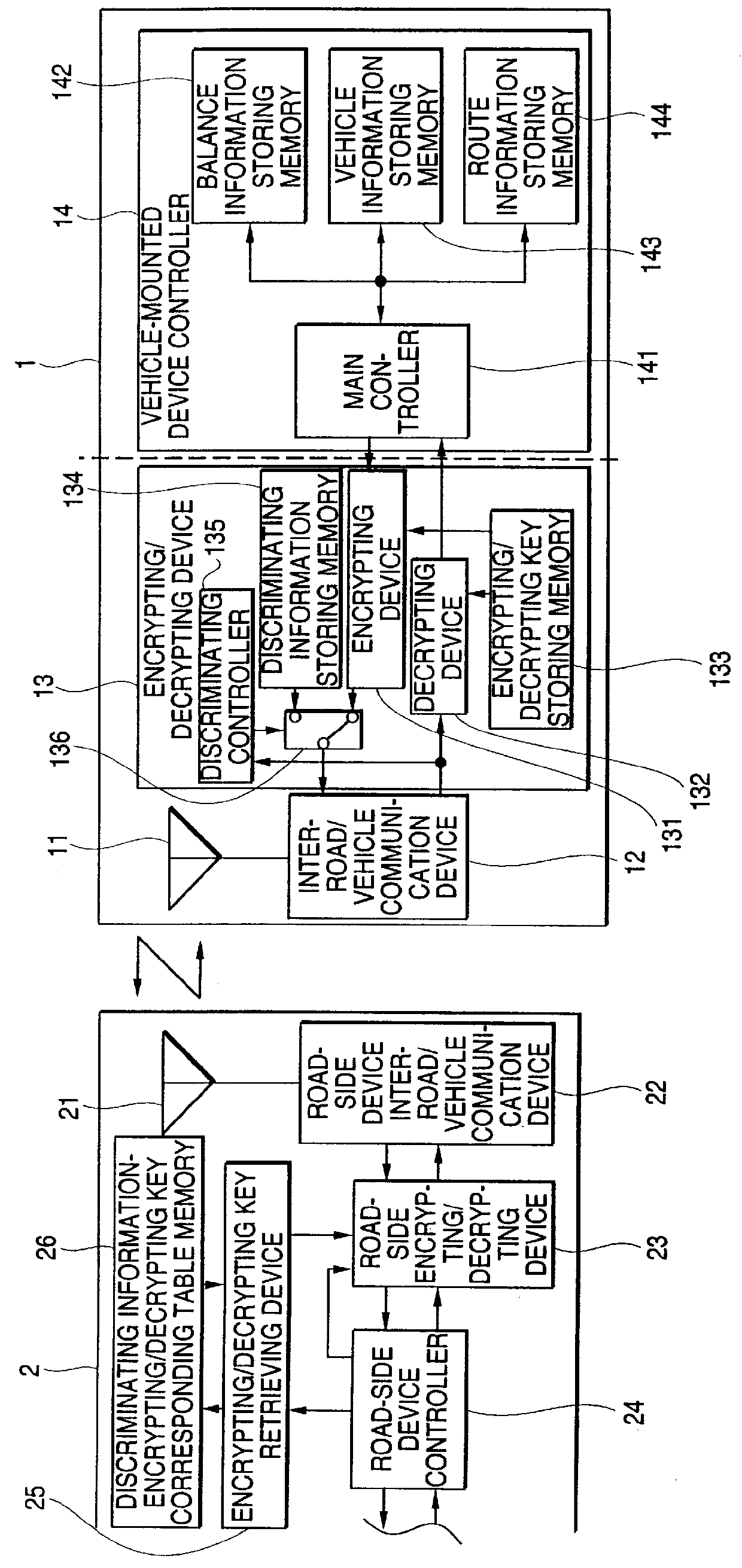
A first preferred embodiment of a vehicle-mounted device of an automatic charge receipt system of the present invention will be described with respect to FIG. 1. In FIG. 1, reference numeral 1 denotes an entire vehicle-mounted device and reference numeral 2 denotes a road-side device. The vehicle-mounted device 1 is comprised of: an antenna 11 for communicating with the road-side device 2; an inter-road / vehicle communication device 12 connected to the antenna 11; a vehicle-mounted device controller 14 for processing a charge receipt; and an encrypting / decrypting device 13 placed between a vehicle-mounted device controller 14 and the inter-road / vehicle communication device 12. The encrypting / decrypting device 13 is comprised of: a...


PUM


Abstract

A vehicle-mounted device for an automatic charge receipt system capable of being designed, manufactured and installed while an encrypting / decrypting algorithm and / or encrypting / decrypting keys remain hidden. Included is an arrangement for discrimination (i.e., identification) of a vehicle-mounted device or user each time a utilization charge is determined / settled, wherein an initial portion of communications concerning discrimination is conducted without encrypting / decrypting, and remaining portions of communications are conducted with encrypting / decrypting so as to protect an integrity and security of the automatic charge receipt system. Confindential components / information, e.g., the encrypting / decrypting algorithm and / or keys, and components directly handling such information are arranged within a tamper- / access-resistant unit (preferably as a sealed integrated circuit package) in the vehicle-mounted device. Since an encryptor and a decryptor directly read the encrypting / decrypting key without such key being detectable outside of the sealed unit, it is not necessary for components outside the sealed unit to receive and / or handle the aforesaid encrypting / decrypting key or their contents. Accordingly such key remains hidden (i.e., inaccessable) within the sealed unit. The arrangement can further include an authentication protocol such as a 3-way authentication protocol, a 2-wayx2 authentication protocol and a Fiat-Shimir authentication protocol.

Description

1. Field of the InventionThis invention relates to an automatic charge receipt system for automatically collecting a utilization (i.e., toll) charge pertaining to vehicle / use information and utilization charge information as communicated between a vehicle running on a utilization charge road (i.e., toll road) and a road-side device (toll booth) installed in a road-side system, and to a vehicle-mounted device to be installed on the vehicle for effecting such communication.2. Description of Related ArtIn recent years, there has been studied an automatic charge receipt system for automatically collecting a charge (i.e., toll) from a vehicle running on a charged road. This technology is operated such that a road-to-vehicle communication is carried out using an electromagnetic wave communication between a vehicle-mounted device installed on the vehicle and a road-side device installed in a road-side system (e.g., toll both) so as to exchange information about charge payment so as to dete...

Claims


Application Information

Patent Timeline
Patent Type & Authority Patents(United States)
IPC IPC(8): G08G1/017G07B15/00B60P3/00H04L9/10
CPCG07B15/063G08G1/017
Inventor KOBAYASHI, KENJISAKAMOTO, TOSHIYUKITANAKA, YASUNARI
Owner HITACHI LTD
Why Eureka
Try Eureka