Image coding and decoding method and related apparatus

a dynamic image and decoding technology, applied in the field of dynamic image coding and decoding methods, can solve the problems of affecting the decoding operation of the bit string after the first sync word, the possibility of failing to decode the bit string after an error occurrence is higher, and the decoding of the bit string becomes impossible after an error occurren

Inactive Publication Date: 2000-07-18
PANASONIC CORP
View PDF8 Cites 6 Cited by
  • Summary
  • Abstract
  • Description
  • Claims
  • Application Information

AI Technical Summary

Problems solved by technology

Hence, the coding block located at the rearward part of the bit string has a higher possibility of being failed in a decoding operation.
The micro block located in a rearward part of the bit string succeeding the first sync word has a higher possibility of being failed in the decoding operation.
However, the above-described system comprises the following problems. FIG. 8, like FIG. 7, shows an arrangement of a bit string transmitted from the transmitter of the above-described system wherein an error is involved.
From the nature of variable-length codes constituting the bit string, decoding the bit string after an occurrence of an error becomes impossible.
Needless to say, the copy information may also be subjected to an error.
As described above, there is a possibility that, once an error occurs, the variable-length coded string cannot be decoded at a region following the occurrence of the error.
This is disadvantageous in that the transmitted information cannot be effectively used.

Method used


Image

  • Image coding and decoding method and related apparatus
  • Image coding and decoding method and related apparatus
  • Image coding and decoding method and related apparatus

Examples


Embodiment Construction

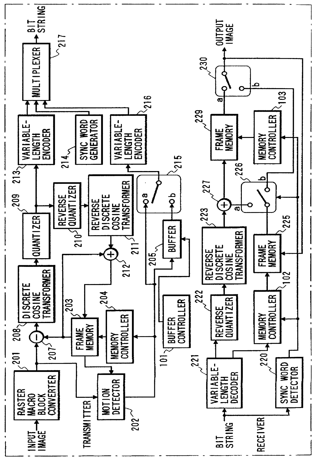
Hereinafter, a preferred embodiment of the present invention will be explained with reference to the accompanied drawing. FIG. 1 shows an arrangement of an image coding and decoding apparatus in accordance with a preferred embodiment of the present invention. The arrangement shown in FIG. 1 is basically the same as that disclosed in FIG. 5. The identical parts are denoted by the same reference numerals throughout the view. In a transmitter shown in FIG. 1, a raster macro block converter 201 serves as a block split means for converting an input image into a plurality of macro blocks. A motion detector 202 detects a motion vector representing a shift amount of a present macro block based on a comparison between the present macro block image and a corresponding past image. A frame memory 203 stores an image reproduced one frame before and supplies the stored image to the motion detector 202 to detect the motion vector. A memory controller 204 controls the read and write operations of f...


PUM


Abstract

In a transmitter, a motion detector detects a motion amount of a coded block. A buffer memorizes a detected motion amount. A buffer controller controls the buffer to read the motion amounts in the order opposed to the writing order. A switch selects one of outputs. In a receiver, a sync word detector discriminates first and second sync words. A primary frame memory memorizes an actually decoded image. A secondary frame memory memorizes a predicted image corresponding to the actually decoded image. Memory controllers read out the image information of coding blocks from the corresponding frame memories in an order opposed to the writing order. A switch selects either one of the information of the primary or secondary frame memories.

Description

1. Field of the InventionThe present invention relates to a dynamic image coding and decoding method and a related apparatus for compressing and expanding digitized dynamic image signals, and more particularly to a method and an apparatus robust against an error occurring during a transmission.2. Prior ArtFirst, a conventional image coding and decoding method will be explained schematically. A motion compensate / predict coding method and a variable-length coding method are conventionally known as fundamental techniques for coding and decoding dynamic images. A copy information method is a transmitting technique capable of increasing the robustness against a transmission error occurring on a transmission line. FIG. 6 shows a quarter common input format (abbreviated QCIF) which is used worldwide as a standard format for a dynamic image. The quarter common input format shown in FIG. 6 represents a brightness signal of lateral 176 pixels by vertical 144 pixels. In general, an input image...

Claims


Application Information

Patent Timeline
Patent Type & Authority Patents(United States)
IPC IPC(8): G06T9/00H04N7/36H04N7/50H04N19/60G06T1/60G09G5/00H04L1/08H04N1/415H04N19/423H04N19/46H04N19/51H04N19/625H04N19/65H04N19/66H04N19/70H04N19/85H04N19/88H04N19/91
CPCH04N19/51H04N19/61H04N19/65
Inventor IMURA, KOJI
Owner PANASONIC CORP
Why Eureka
Try Eureka