Removable chain hoist position encoder assembly

a technology of encoder assembly and chain hoist, which is applied in the direction of hoisting equipment, measuring wheels, instruments, etc., can solve the problems of inability to adjust the position of the hoist using manual controls, inability to observe the hoist visually, and inability to easily provide the services of such individuals, etc., and achieves the effect of reducing the cost of such individuals' services and often not readily availabl

Inactive Publication Date: 2001-04-03
GEORGE & GOLDBERG DESIGN ASSOC
View PDF15 Cites 59 Cited by
  • Summary
  • Abstract
  • Description
  • Claims
  • Application Information

AI Technical Summary

Problems solved by technology

Where precision control of a chain hoist is necessary, visual observation and corresponding adjustment utilizing manual controls is very inadequate and unacceptable.
While such conventional position-encoding systems do provide the required positional information, they have significant disadvantages.
The services of such individuals are expensive and often are not readily available.
A further significant disadvantage of such conventional chain hoist encoder systems is that once the chain hoist casing is opened, the manufacturer's warranty for the chain hoist is voided.
This is only reasonable since if a person without sufficient expertise attempts to install a position encoder within the casing of a chain hoist, connections can easily be made or broken that will cause permanent damage to the chain hoist and cause it to malfunction.
Moreover, tampering with the internally protected components of a chain hoist by persons lacking sufficient expertise can result in alterations to the chain hoist that can cause vary hazardous malfunctions.
This can lead to significant property damage and personal injury when the chain hoist is thereafter operated.
Chain hoists that are produced by different manufactures, and even different models of chain hoists produced by the same manufacturer, often have significant differences in their operating components and external configuration.
However, there are only a very limited number of different chain sizes and configurations with which conventional, general purpose chain hoists are utilized commercially.

Method used


Image

  • Removable chain hoist position encoder assembly
  • Removable chain hoist position encoder assembly
  • Removable chain hoist position encoder assembly

Examples


Embodiment Construction

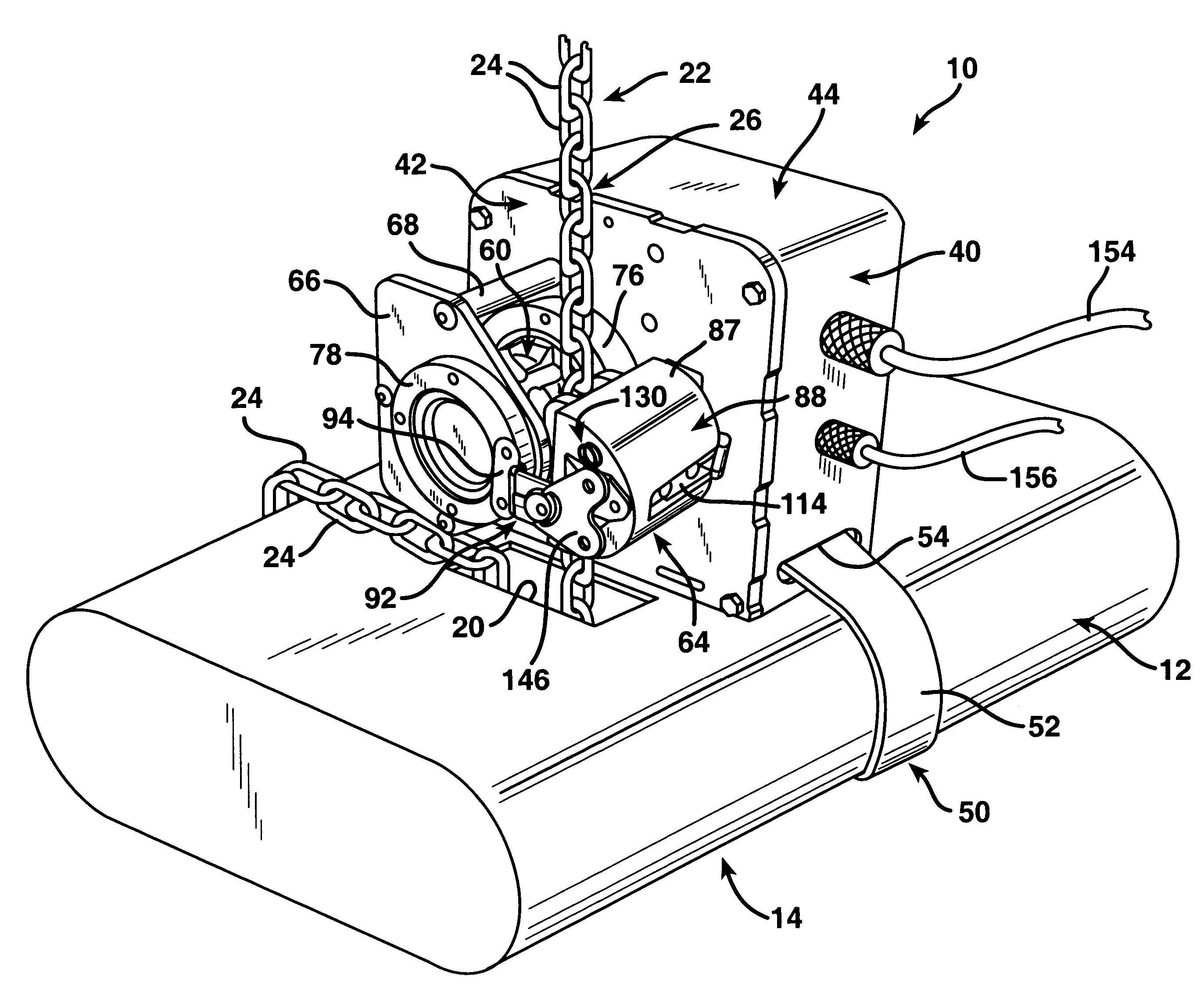
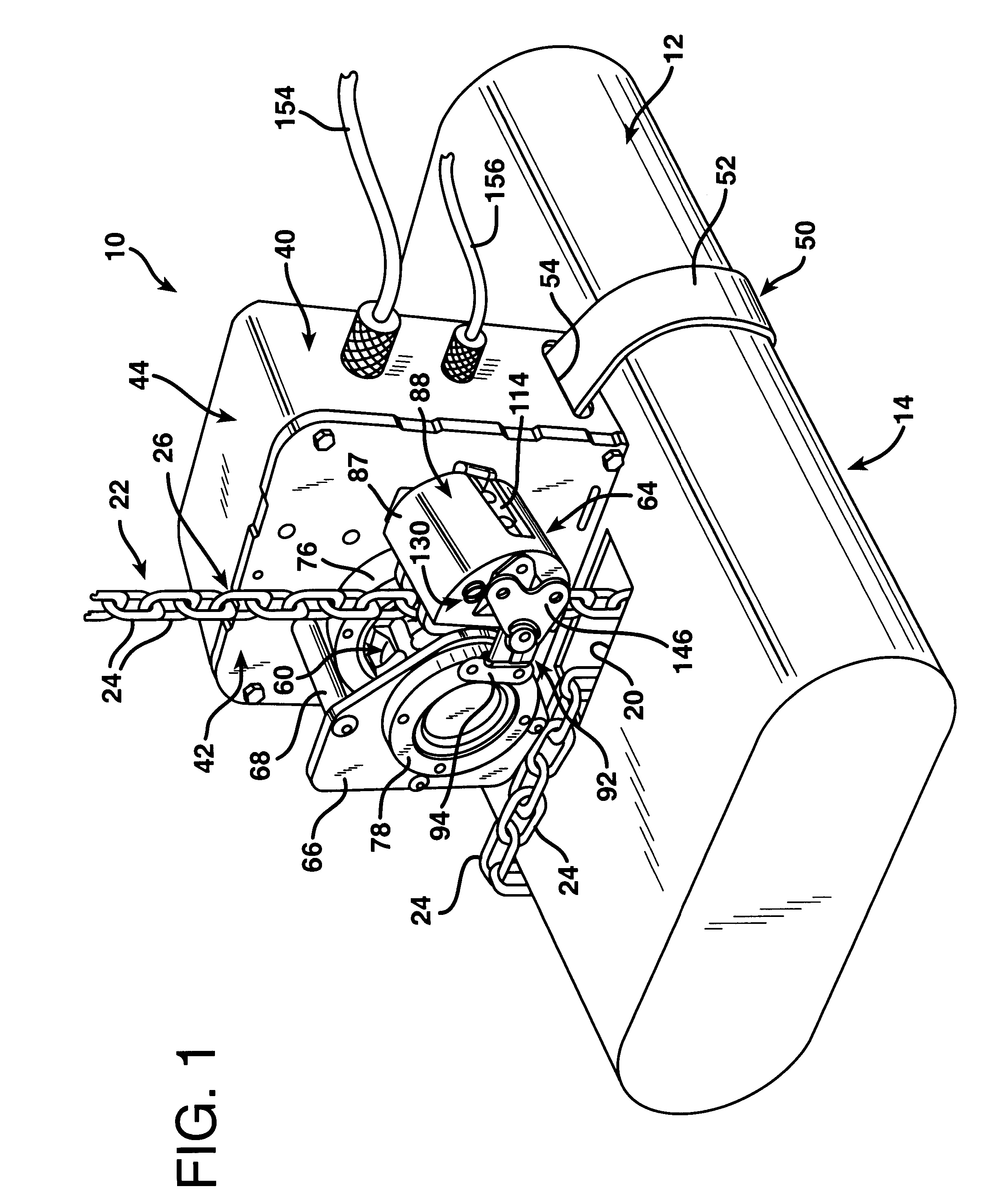
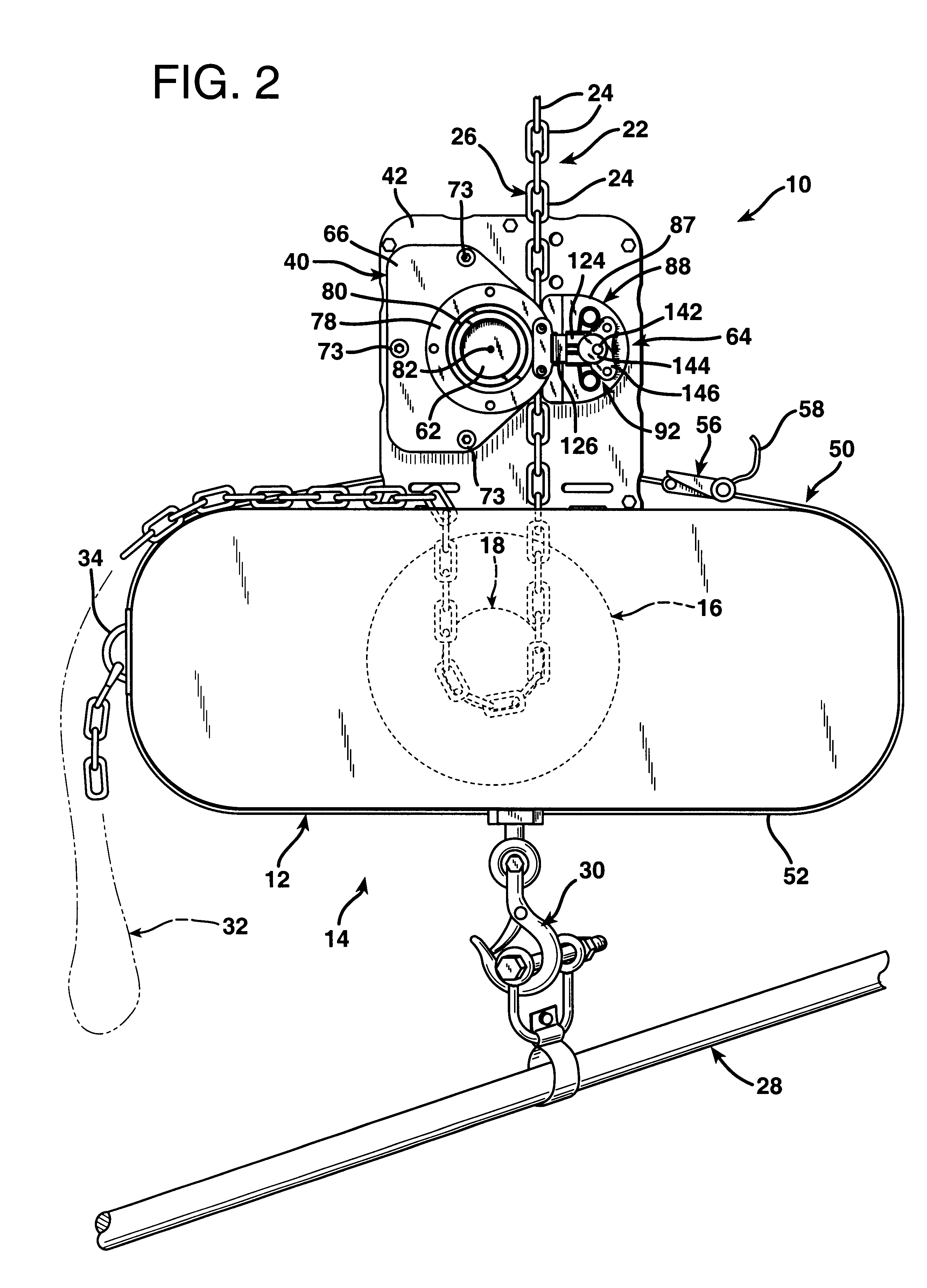
FIGS. 1 and 2 illustrate a dual sensor position encoder assembly 10 according to the invention removably mounted externally atop the casing 12 of a conventional, general purpose chain hoist 14. The casing 12 of the chain hoist 14 is a rugged, durable, encompassing steel shell that encloses a chain hoist motor 16 and an internal chain hoist drive gear 18 therewithin. The chain hoist motor 16 and the internal chain hoist drive gear 18 are conventional and are illustrated in phantom in FIG. 2. The chain host motor 16 is rigidly mounted within the casing 12 and the internal chain hoist drive gear 18 is fixed to the drive shaft of the motor 16.

As best illustrated in FIG. 1, the chain hoist casing 12 has a rectangular chain access opening 20 defined therein. In the arrangement illustrated in FIGS. 1 and 2, the chain hoist 14 is suspended from an overhead support (not shown) in a conventional manner by a chain 22 having a multiplicity of chain links 24. The links 24 are each formed as oblo...


PUM


Abstract

A chain hoist having a casing into which and with respect to which a chain travels is provided with an externally mounted position encoder assembly. A releasable connector, such as a ratchet strap, is employed to firmly but removably couple the position encoder assembly housing externally on the chain hoist casing. The releasable connector holds the position encoder assembly housing in a fixed position relative to the chain hoist casing. The position encoder assembly has a chain gear that is rotatably mounted relative to the position encoder assembly housing proximate to the chain access opening in the chain hoist casing. The precision encoder assembly chain gear engages the portion of the chain that is maintained under tension at a location externally of the chain hoist casing and rotates as the chain travels relative to the chain hoist casing. A releasable clamp is anchored relative to the position encoder assembly housing and is engageable to maintain engagement of the position encoder assembly chain gear with the chain. An encoder is mounted with respect to the position encoder assembly housing and detects rotational movement of the position encoder assembly chain gear. The sensor provides electrical output signals indicative of the extent and direction of rotational movement of the position encoder assembly chain gear. The position encoder assembly provides precise, reliable output signals indicative of the position of the chain relative to the chain hoist. The position encoder assembly may be readily removed from the chain hoist, and just as easily attached thereto.

Description

1. Field of the InventionThe present invention relates to a chain hoist position encoder assembly which may be removably attached externally on the casing of a chain hoist to track the movement of the load carried by the chain hoist relative to a fixed location.2. Description of the Prior ArtChain hoists are utilized in many different applications to raise and lower loads suspending from overhead supports. A chain hoist is comprised of a heavy-duty motor housed within a rugged casing and having at least one chain access opening in the casing. A chain may be suspended from an overhead support or from the chain hoist itself to carry a load. In either case the chain is routed around a chain drive gear located within the chain hoist casing. The chain drive gear within the casing is driven by the chair hoist motor. The slack portion of the chain, after passing around the drive gear within the casing, is routed back out through the chain opening and hangs from the chain hoist casing as a ...

Claims


Application Information

Patent Timeline
Patent Type & Authority Patents(United States)
IPC IPC(8): B66D3/26B66D3/18B66D3/00
CPCB66D3/18B66D3/26
Inventor GEORGE, DAVID W.GUTH, CHRISTOPHER E.MORGAN, IVAN J.BRACEGIRDLE, GLENN R.BOOTH, THOMAS G.ROMANO, RICHARD J.FRY, ROBERT A.
Owner GEORGE & GOLDBERG DESIGN ASSOC
Why Eureka
Try Eureka