Auto-returning height-control assembly for a chair

a technology of height control and assembly, which is applied in the direction of chairs, stands/trestles, kitchen equipment, etc., can solve the problems of time and manpower consumption in doing all chairs, inconvenient seating arrangement of chairs,

Inactive Publication Date: 2001-11-13
SAMHONGSA
View PDF7 Cites 46 Cited by
  • Summary
  • Abstract
  • Description
  • Claims
  • Application Information

AI Technical Summary

Benefits of technology

A projection is formed at a certain location of the outer cylinder and a washer is inserted between the projection and the elastic member in order to limit the moving direction of the elastic member. A ring in which more than one penetration hole is formed and a thrust bearing are installed between the elastic member and the second cam member and a spacer of a taper form which is fixed with the outer cylinder is installed at the lower part of the elastic member. The spacer, sleeve member, ring and the washer can be made of aluminum alloy, metal, metalloid and resin.

Problems solved by technology

Therefore, there is inconvenience in arranging seats of chairs into their original places after using them, and especially, when there are larger number of chairs, it is time and manpower consuming to do all the chairs.

Method used


Image

  • Auto-returning height-control assembly for a chair
  • Auto-returning height-control assembly for a chair
  • Auto-returning height-control assembly for a chair

Examples


embodiment 1

Preferred Embodiment 1

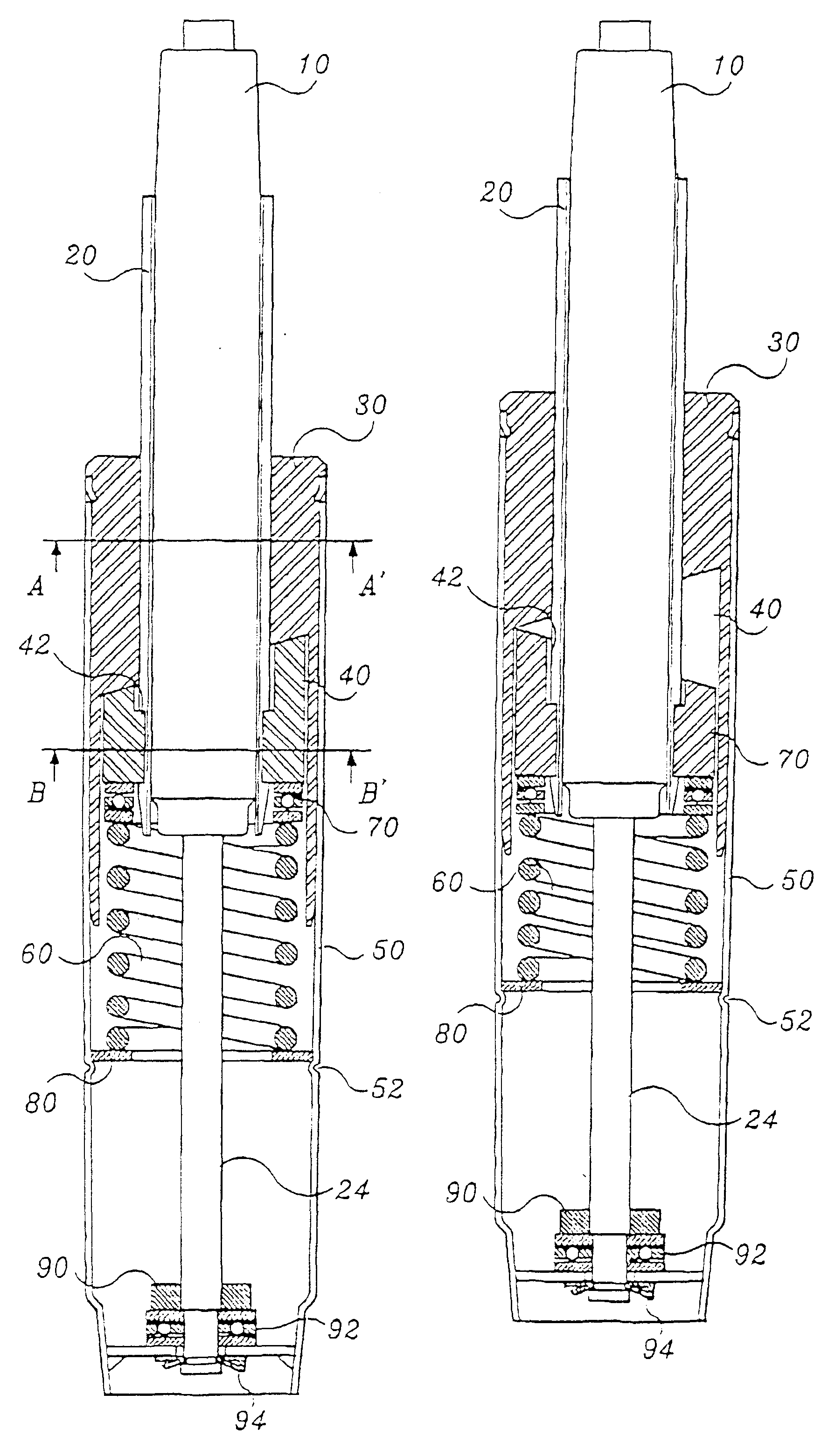
The auto-returning height adjusting control assembly according to the present invention comprises a spindle 10, a sleeve member 20 which covers the body part of the spindle, an upper cam 30 (a first cam member) in which a slope side of cam form is formed at the lower part in which the sleeve member 20 is inserted, a lower cam 40 (a second cam member) which has slope side of cam form corresponding to the slope side of the upper cam 30 at the upper part and which is combined with the sleeve member 20, an outer cylinder 50 in which one end is fixed with the upper cam, and a spring 60 as shown in FIGS. 3 to 9. In particular, the upper cam 30 comprises a first and second cylindrical part which have different diameters as shown in FIGS. 4, 8, and 9. The lower cam 40 is located inside the second cylindrical part of the upper cam.

The groove 22 is formed along the length direction at the outer cylindrical surface of the sleeve member 20 which is combined with the spindl...

embodiment 2

Preferred Embodiment 2

The auto-returning height control assembly of this preferred embodiment comprises a spindle 510, a sleeve member 520 which covers the spindle 510 and which is fixed, an upper cam 530 (a first cam member) in which the sleeve member 520 is inserted and in which a slope side of a cam form is formed, a lower cam 540 (a second cam member) which is combined with the sleeve member and in which a slope side of a cam form corresponding to the cam form of the upper cam is formed at the upper part, an outer cylinder 550 in which on end is fixed with the upper cam and a spring 560.

The upper cam 530 and the lower cam 540 contact the outer cylinder 550 separately. The upper cam 530 is fixed to the upper part of the outer cylinder 550 and lower cam 540 is structured to move in the direction of the longitudinal axis of the spindle along the inside cylindrical surface of the outer cylinder 550. A groove 522 is formed at the outer cylindrical surface of the sleeve member 520 whi...


PUM


Abstract

An auto-returning height control assembly comprising a spindle which is inserted in an outer cylinder and one end is fixed to an end of the outer cylinder, and a first and second cam member which are inserted between the outer cylinder and a sleeve member so that the spindle can rotates about its longitudinal axis and returns; its original place at the same time. At least one projection is formed on the sleeve member and the first cam member is fixed at the inside cylindrical surface of the outer cylinder. A projection is formed on the second cam member and the projection is inserted into the groove of a sleeve member and allows the up and down movement against the sleeve member. A spring is installed at the lower part of the second cam member to push the second cam member towards the first cam member.

Description

1. Field of the InventionThe present invention is related to an auto-returning height-control assembly for a chair wherein a chair returns to its original place automatically when a person stands up from a chair or sits down on a chair and turns the chair.2. Description of the Background InventionFIG. 1 is a vertical cross sectional view which shows a conventional height adjusting assembly for a chair. The conventional height adjusting assembly comprises a outer cylinder 600, a spindle guide 500 which is inserted and fixed inside the outer cylinder 600 and a spindle 150 which slides along the inside surface of the spindle guide 500.The spindle 150 is connected with a piston rod 110 and extends outwards toward the outer cylinder. The height of the spindle is adjustable along the axis of the piston rod and a push button (133), which is put on and off to make the spindle move up and down along the axis of the piston rod, is installed at an outer end of the spindle. An end of the piston...

Claims


Application Information

Patent Timeline
Patent Type & Authority Patents(United States)
IPC IPC(8): A47C3/20A47C3/30
CPCA47C3/18A47C3/185A47C3/30A47C3/20
Inventor HUR, SONG
Owner SAMHONGSA
Why Eureka
Try Eureka