
Direction changeable stroller

a changeable and stroller technology, applied in the direction of folding cycles, cycles, carts/perambulators with multiple axes, etc., can solve the problems of wheel assemblies that need to be limited, and the directions of the front wheel assemblies

Active Publication Date: 2011-11-24
WONDERLAND SWITZERLAND AG
View PDF1 Cites 18 Cited by
  • Summary
  • Abstract
  • Description
  • Claims
  • Application Information

AI Technical Summary

Benefits of technology

[0007]The object of this invention is to provide a direction changeable stroller that can automatically limit the direction of front or rear wheels during movement of the stroller.
[0008]According to this invention, a direction changeable stroller comprises a frame unit that includes a side leg frame and a push handle pivotable between front and rear positions. The side leg frame includes front and rear leg tubes, and front and rear wheel assemblies. Each of the front and rear wheel assemblies includes a wheel seat and a wheel. Each of the wheel seats includes a fixed portion connected fixedly to a corresponding one of the front and rear leg tubes, and a rotating portion connected pivotably to the fixed portion. The side leg frame further includes an automatic direction-limiting mechanism connected to the push handle such that, when the push handle is at a selected one of the front and rear positions, relative rotation between the fixed portion and the rotating portion of a corresponding one of the front and rear wheel seats is prevented.
[0009]As such, since the direction of the front or rear wheels can be limited by the automatic direction-limiting mechanism when the stroller is moved, the moving direction of the stroller can be controlled easily.

Problems solved by technology

That is, when the push handle is at the rear position, the directions of wheels of the rear wheel assemblies need to be limited, and when the push handle is at the front position, the directions of wheels of the front wheel assemblies need to be limited.

Method used


Image

  • Direction changeable stroller
  • Direction changeable stroller
  • Direction changeable stroller

Examples


Embodiment Construction

[0022]Before the present invention is described in greater detail in connection with the preferred embodiments, it should be noted that similar elements and structures are designated by like reference numerals throughout the entire disclosure.

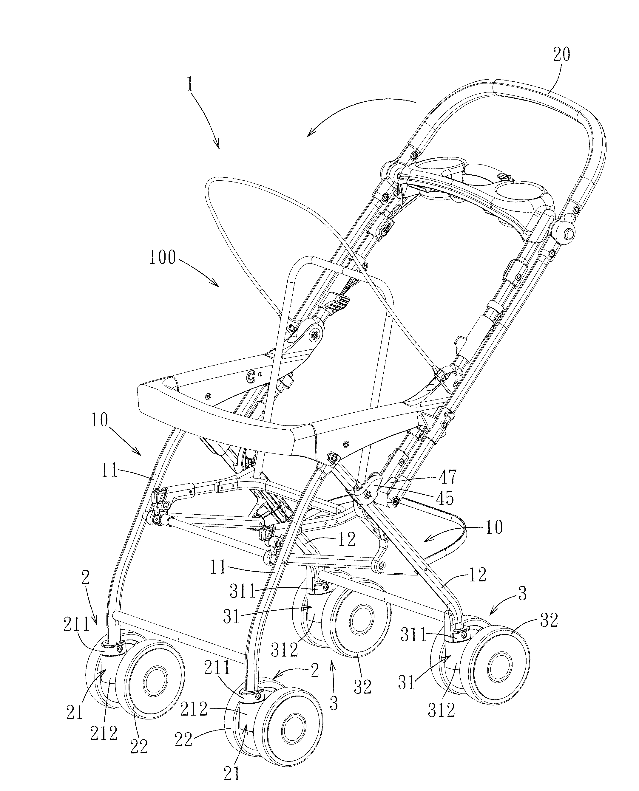
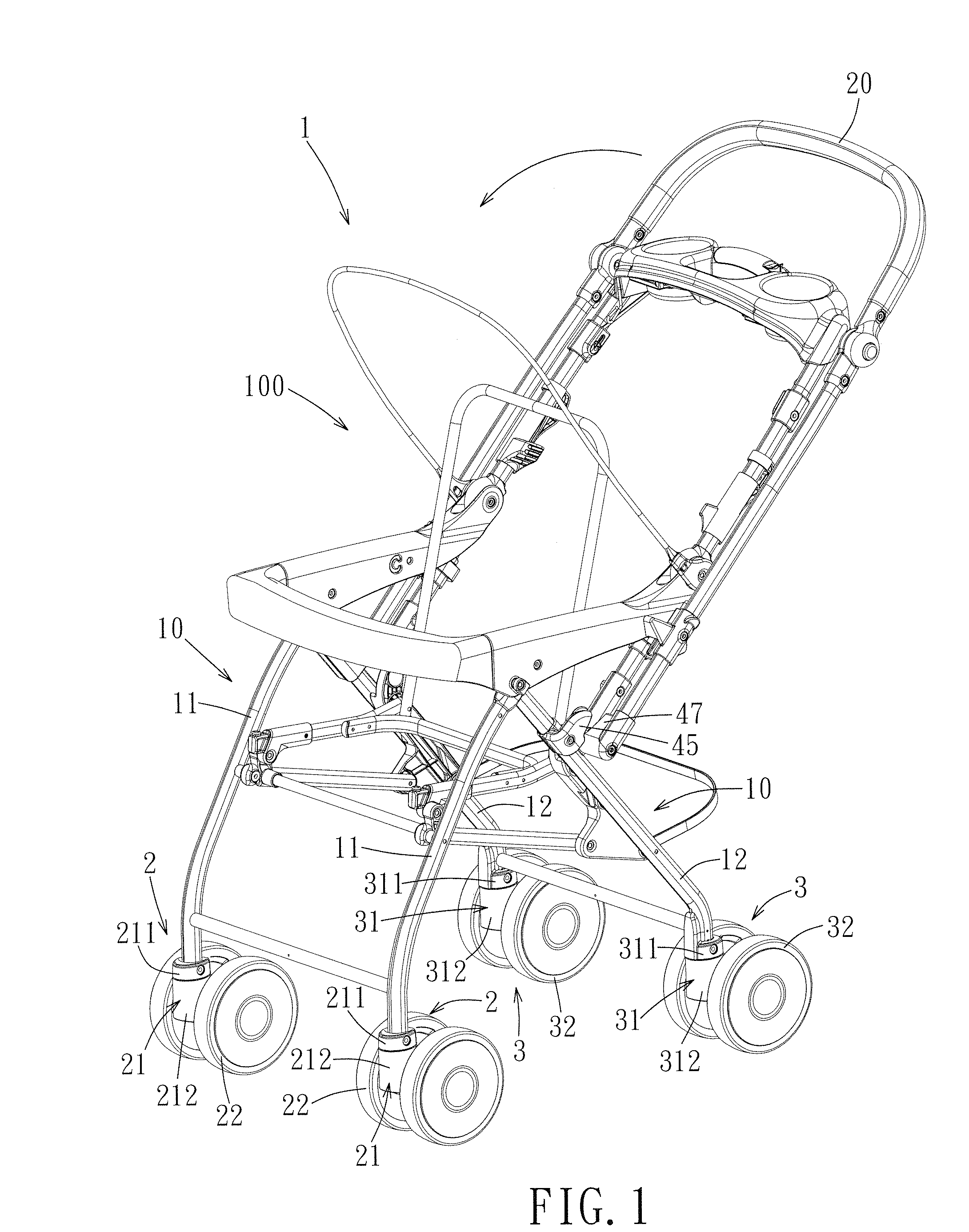
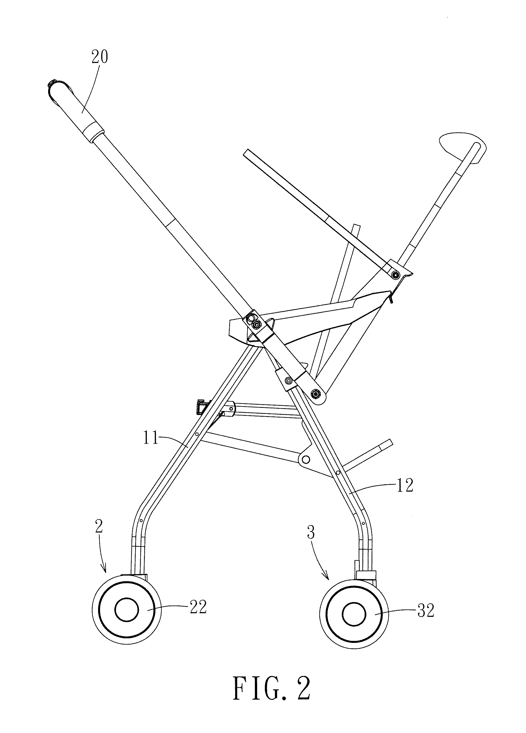
[0023]Referring to FIG. 1, the first preferred embodiment of a direction changeable stroller 1 according to this invention includes a frame unit 100. The frame unit 100 includes two symmetrical side leg frames 10 and a push handle 20. The push handle 20 is pivotable relative to the side leg frames 10 between a rear position (shown in FIG. 1) disposed at a rear end of the stroller 1, and a front position (shown in FIG. 2) disposed at a front end of the stroller 1 and in front of the rear position. Each of the side leg frames 10 includes a pair of front and rear leg tubes 11, 12, a front wheel assembly 2 disposed on a bottom end of the front leg tube 11, and a rear wheel assembly 3 disposed on a bottom end of the rear leg tube 12. The front wheel...


PUM


Abstract

A direction changeable stroller comprises a frame unit that includes a side leg frame and a push handle pivotable between front and rear positions. The side leg frame includes front and rear leg tubes, and front and rear wheel assemblies. Each of the front and rear wheel assemblies includes a wheel seat and a wheel. Each of the wheel seats includes a fixed portion connected fixedly to a corresponding one of the front and rear leg tubes, and a rotating portion connected pivotably to the fixed portion. The side leg frame further includes an automatic direction-limiting mechanism connected to the push handle such that, when the push handle is at a selected one of the front and rear positions, relative rotation between the fixed portion and the rotating portion of a corresponding one of the front and rear wheel seats is prevented.

Description

CROSS-REFERENCE TO RELATED APPLICATION[0001]This application claims priority of Chinese Application NO. 201010179308.9, filed on May 19, 2010.BACKGROUND OF THE INVENTION[0002]1. Field of the Invention[0003]This invention relates to a direction changeable stroller, and more particularly to a direction changeable stroller that can automatically limit the directions of wheels disposed at a trailing side relative to the moving direction of the stroller.[0004]2. Description of the Related Art[0005]A conventional direction changeable stroller includes a push handle that can be changed between front and rear positions. When the push handle is disposed at the rear position, the baby seated on the stroller faces forwardly. When the push handle is disposed at the front position, the baby faces rearwardly toward the person pushing the stroller. The push handle can be disposed at a selected one of the front and rear positions according to the user's need during use.[0006]However, the convention...

Claims


Application Information

Patent Timeline
Patent Type & Authority Applications(United States)
IPC IPC(8): B62B7/06
CPCB62B7/042B62B2301/0463B62B9/203
Inventor XU-HUI, CHENSHUN-MIN, CHEN
Owner WONDERLAND SWITZERLAND AG
Learn More