Connection between a dental implant and an abutment

a technology of connecting abutments and dental implants, applied in dental implants, dental surgery, medical science, etc., can solve the problems of limiting the size of insertable occlusal screws, and cannot, however, be considered the ultimate, complete solution, and achieve the effect of high functional reliability and efficient production costs

Inactive Publication Date: 2003-12-16
STRAUMANN HLDG AG
View PDF13 Cites 166 Cited by
  • Summary
  • Abstract
  • Description
  • Claims
  • Application Information

AI Technical Summary

Benefits of technology

In view of the need to improve the functional reliability of the previously known connection arrangement and at the same time lower the production outlay, the invention is based on the object of proposing a perfected connection arrangement. A connection arrangement between an implant and a straight or angled abutment that is distinguished by extremely high reliability is to be provided. The abutment must at the same time allow itself to be fixed in a practical way on the implant and must not be loosened even as a result of micro-movements. Moreover, the connection arrangement is to comprise a small number of uncomplicated parts and consequently be inexpensive to produce. The parts of the connection arrangement should have a system character and consequently be able to be used for different variants of the connection arrangement--i.e. for combination with various abutments. The main advantages of a connection arrangement where the base screw is inserted with the screw head first into the root part of the abutment are to be retained. An additional objective here is that the flexurally greatly stressed base screw should have a small longitudinal force and a loosening moment that is as high as possible.
It has proven to be favorable to provide the support ring on its upper and lower edges with an internal beveled surface and to shape the part of the screw neck situated beneath the screw head such that it widens conically toward the screw head. Consequently, in the screwed state, a sloping surface of the screw neck presses against the internal beveled surface of the support ring. With the support ring having an identical contour at the upper and lower edges, it does not matter which edge of the support ring is at the top. To give it elasticity, the support ring could have a penetrating vertical slit or partial slits. In a special configuration, the support ring has an internal thread complementing the threaded shank of the base screw, so that the support ring must be screwed on when it is fitted onto the base screw.
The invention is responsible for providing a connection arrangement between an implant and an abutment which is distinguished by very high functional reliability--i.e. being held together in a stable and precise manner in the fitted state--and advantageous fitting and removal properties. The connection arrangement according to the invention can be produced at efficient production costs and is suitable in particular for implants with a non-rotationally-symmetrical receiving contour in combination with straight or angled abutments with a corresponding non-rotationally-symmetrical outer mating contour.

Problems solved by technology

The space available on the superstructure, for example on the artificial tooth crown, limits the size of the insertable occlusal screw.
The forming of the internal radial groove in the abutment and the use of the spreading ring disposed on the base screw and received in the radial groove cannot, however, be regarded as the ultimate, complete solution.

Method used


Image

  • Connection between a dental implant and an abutment
  • Connection between a dental implant and an abutment
  • Connection between a dental implant and an abutment

Examples


first embodiment

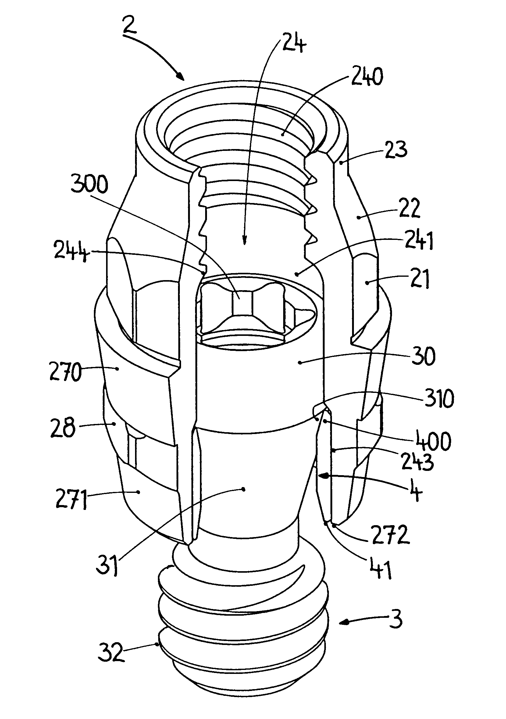
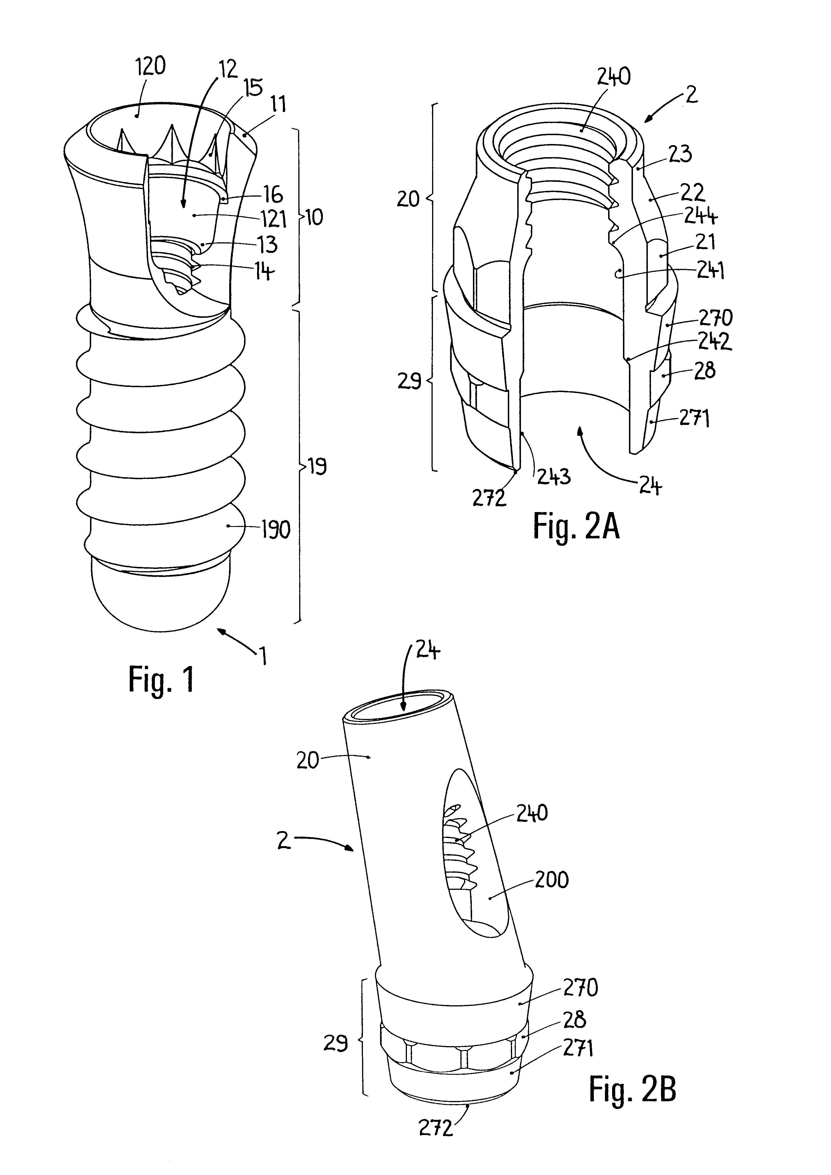
This straight abutment 2 of a first embodiment has at the top the neck part 20 and the downwardly adjoining root part 29, which is conical in certain portions. Said root part is intended for insertion into the receiving hole 12 of the implant 1, while the neck part 20 protrudes above the implant shoulder 11. The neck part 20 is divided into three segments, to be specific the polygonal segment 21 directly adjoining the root part 29--here an external octagon--, the cylindrical guiding segment 23 at the very top and the cone segment 22 lying between the polygonal segment 21 and the guiding segment 23. The polygonal segment 21 is useful for reproducible positioning when taking impressions and making models and also for possible rotational securement of the fitted-on superstructure. The guiding segment 23 contributes to the centering and guiding of the fitted-on crown cap.

On the root part 29 there is a mating contour complementing the receiving contour 15 in the implant 1, consequently h...

third embodiment

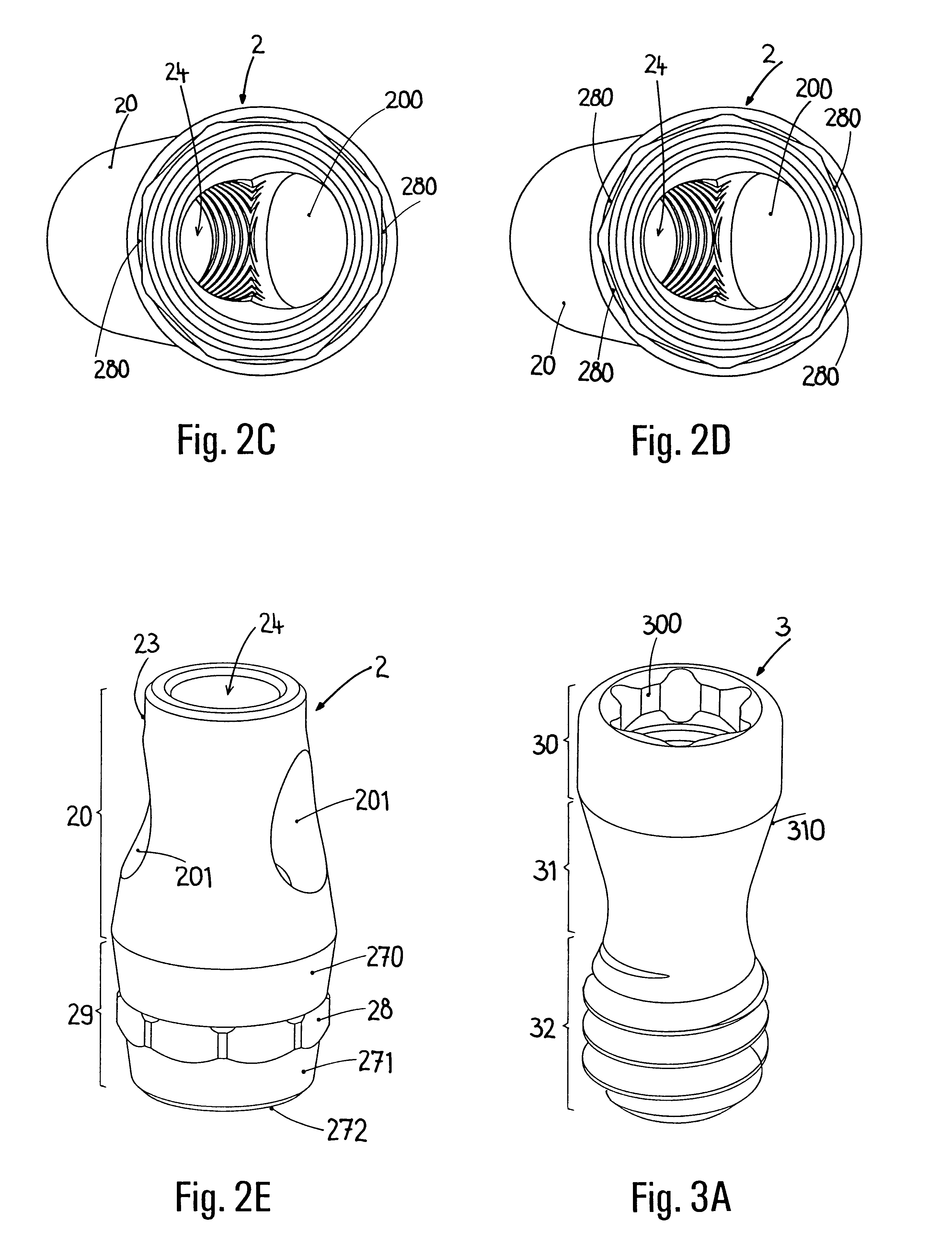
The abutment 2 of the third embodiment has a conical neck part 20, which adjoins the unchanged root part 29 in a straight manner and advantageously terminates at the very top with a cylindrical guiding segment 23. On the neck part 20 there are two lateral openings 201 for transversal screw connection with a fitted-on crown cap. The lateral openings 201 are preferably offset from alignment with respect to one another by 22.5.degree.. Consequently, 16 rotational positions of a transversal cap 7 fitted onto the implant 1 and the abutment 2 are available (see FIG. 6C). This makes better adaptation to the anatomical conditions encountered possible, which is relevant in particular when replacing an individual tooth.

FIG. 3A

For the construction of the connection arrangement according to the invention on the implant 1, alternatively one of the embodiments described above of the abutment 2--the neck part 20 could have further modifications--and a base screw 3 are required. Considered in the d...


PUM


Abstract

The invention relates to a connection between a known dental implant (1) and a straight or angular abutment (2) which can be established by means of a base screw (3) and a support ring (4). The support ring (4) is fixedly introduced into the inlet of the abutment (2) near the lower edge of same, preferably by welding or by bending over of the lower edge of the abutment (2). Before insertion of the support ring (4) the base screw (3) is introduced head first into the inlet (24) from the side of the root part of the abutment. The base screw is held in the abutment (2) by the support ring (4) on which the base screw (3) rests. The threaded shank (32) of the base screw (3) engages the inner thread (14) provided for in the implant (1) and draws the abutment (2) into the receiving hole (12) of the implant (1). An angled surface of the base screw (3) and a beveled surface of the support ring (4) contact each other so that the welding seam or bent over lower edge of the abutment (2) are relieved of axial stress. The above connection system is designed especially for implants (1) with a conical receiving hole (12) and internal polygon as well as abutments (2) having a complementary external conical shape and external polygon.

Description

FIELD OF APPLICATION OF THE INVENTIONThe present invention relates to a connection arrangement which comprises a dental implant known per se, which can be inserted into the jaw bone, and an abutment to be fixed on the implant. At the top, on the head of the implant, an axial, downwardly extending receiving hole, which is preferably widened conically upward, opens out within an encircling implant shoulder. The lower root part of the abutment, which, when there is a conical inner configuration of the receiving hole, has a complementary conical outer contour, can be inserted into the receiving hole. For the reproducible positioning of the abutment, a non-rotationally-symmetrical receiving contour may be advantageously provided in the receiving hole and have relating to it a corresponding, non-rotationally-symmetrical outer mating contour on the root part of the abutment. The non-rotationally-symmetrical contours complementing one another likewise represent a rotational securement for t...

Claims


Application Information

Patent Timeline
Patent Type & Authority Patents(United States)
IPC IPC(8): A61C8/00
CPCA61C8/005A61C8/0069A61C8/0066A61C8/0054
Inventor SCHAR, ALEXGRANDE, VINCENZOMUNDWILER, ULRICH
Owner STRAUMANN HLDG AG
Why Eureka
Try Eureka