Electric connector

Active Publication Date: 2005-02-08
MOLEX INC
View PDF8 Cites 2 Cited by
  • Summary
  • Abstract
  • Description
  • Claims
  • Application Information

AI Technical Summary

Benefits of technology

The present invention has been accomplished under the circumstances in view. It is therefore the main object of the present invention to provide an electric connector, which contacts the contacts of the matching circ

Problems solved by technology

Further, the contact of sli

Method used


Image

  • Electric connector
  • Electric connector
  • Electric connector

Examples


Example

Referring to FIGS. 5˜7, an electric connector is installed in an electronic apparatus (not shown) and electrically connected to the contacts 20 of a circuit board 2 inside the electronic apparatus. The electric connector 1 comprises an electrically insulative housing 10 and a plurality of terminals 11.

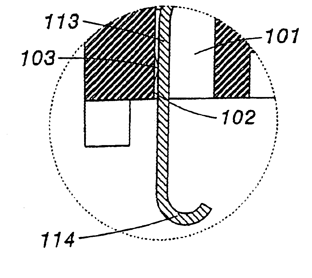
The housing 10 is injection-molded from plastics, comprising a plurality of terminal slots 100. Each terminal slot 100 has a bottom end terminating in a narrow passage 101 cut through the bottom side of the housing 10. The narrow passage 101 has one bearing sidewall 102 (see FIG. 7A). The other part of each terminal slot 100 is similar to the conventional designs.

The terminals 11 are respectively mounted in the terminal slots 100 of the housing 10, each having a positioning portion 110 positioned in the corresponding terminal slot 100, a top contact arm 111 extended from one side, namely, the top side of the positioning portion 110 and adapted to contact one contact of an external elec...


PUM


Abstract

An electric connector formed of an electrically insulative housing and terminals installed in respective terminal slots of the housing is disclosed in which each terminal has a U-shaped springy supporting portion supported inside one terminal slot of the housing, a vertical arm downwardly extended from one end of the U-shaped springy supporting portion, and a contact tip extended from the bottom end of the vertical arm suspended outside the housing for the contact of a corresponding contact of a circuit board.

Description

FIELD OF THE INVENTIONThe present invention relates to electric connectors and, more particularly, to such an electric connector, which effectively reduces the installation space of the matching circuit board and, achieves a satisfactory electric connection effect.DESCRIPTION OF THE RELATED ARTFIG. 1 shows an I / O (Input / Output) electric connector 1a for use in an electronic apparatus. This structure of electric connector 1a comprises an electrically insulative housing 10a, and a plurality of terminals 11a mounted in respective terminal slots 12a in the housing 10a. With reference to FIGS. 1 and 2, each terminal 11a comprises a cured springy supporting portion 13a, a contact tip 15a suspending outside the housing 10a, and a straight bearing arm 14a connected between the springy supporting portion 13a and the contact tip 15a. During installation, the contact tip 15a is maintained in contact with a respective contact 20a of the circuit board 2a inside the electronic apparatus.The afore...

Claims


Application Information

Patent Timeline
IPC IPC(8): H01R13/41H01R13/40H01R13/24H01R13/22H01R12/04
CPCH01R12/716H01R13/24H01R12/714H01R13/41
Inventor YIN, HUNG-JIUNWU, YZ-JIUN
Owner MOLEX INC
Why Eureka
Try Eureka