

Head up display for vehicle
- Summary
- Abstract
- Description
- Claims
- Application Information
AI Technical Summary
Benefits of technology
Problems solved by technology
Method used
Image

Examples
second embodiment
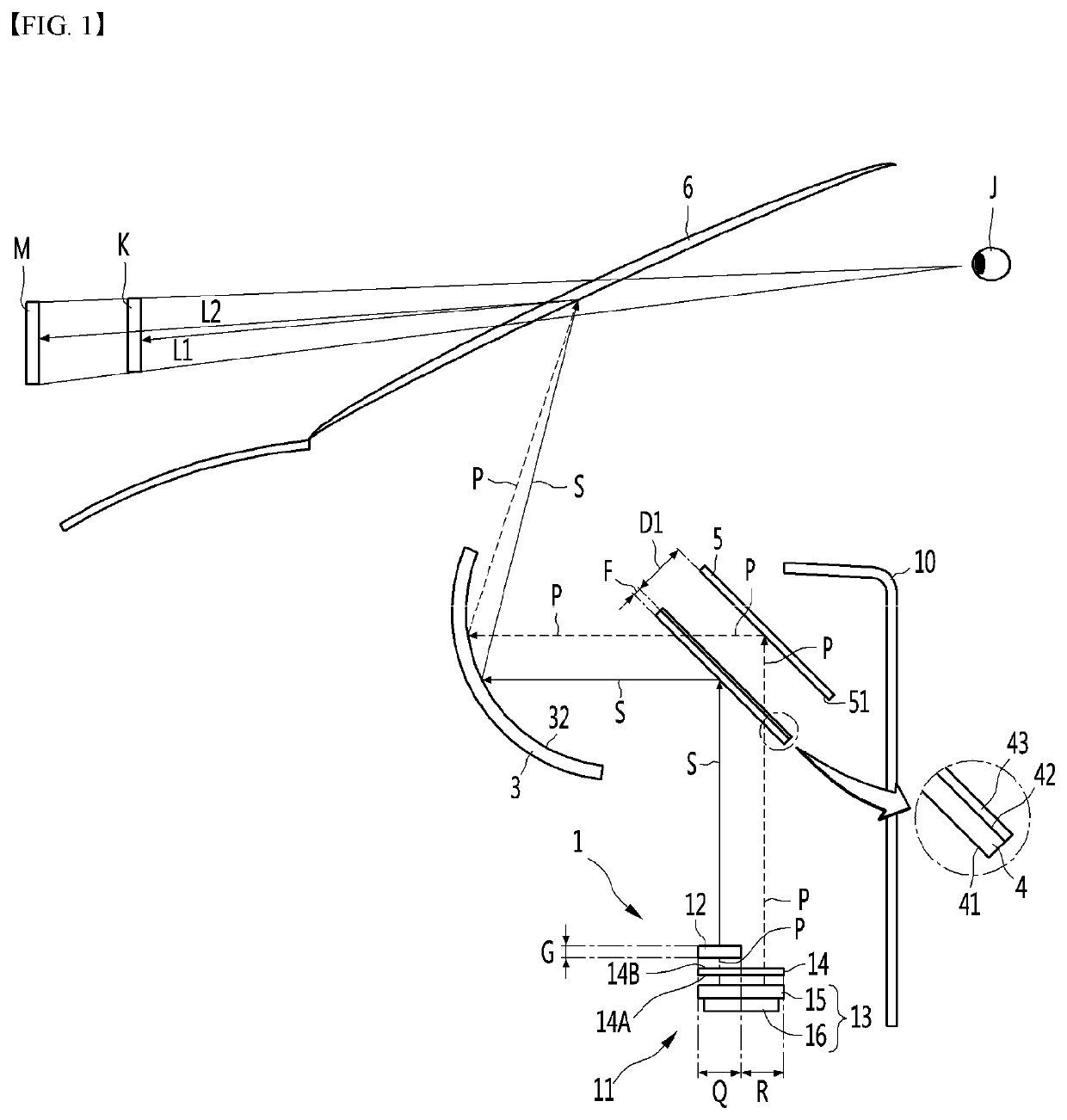
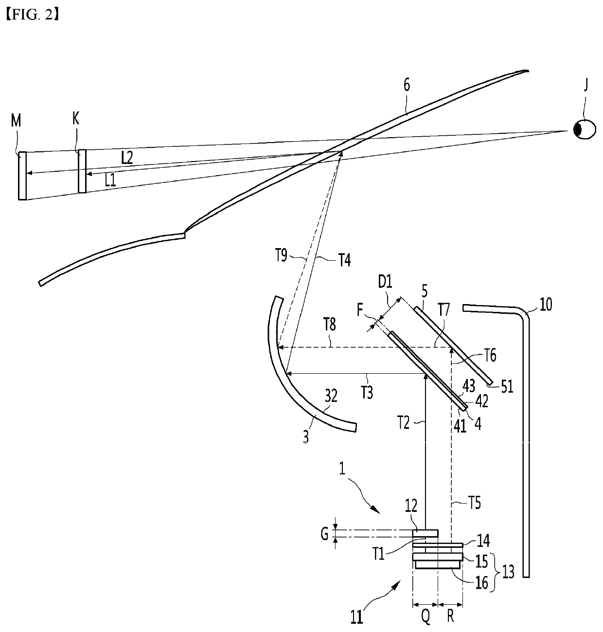
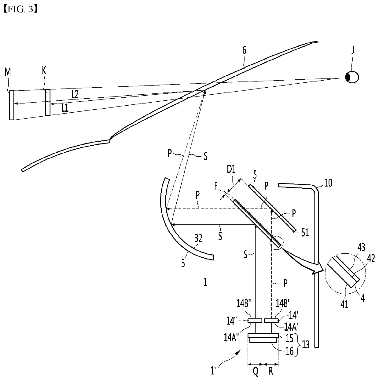
[0128]FIG. 3 is a side view illustrating main components of a head up display for a vehicle according to the present disclosure.
[0129]Only a difference between the present embodiment and the first embodiment of the present disclosure is an imaging mechanism 1′. Other components and operations other than the imaging mechanism 1′ of the present embodiment are the same as or similar to that of the first embodiment of the present disclosure, so that the present embodiment uses the same reference numerals. Further, a detailed description of other components and operations of the present embodiment will be omitted.
[0130]The imaging mechanism 1′ of the present embodiment may include a display panel 13 for emitting the image light, a first linear polarizer 14′ for linearly polarizing the image light emitted from the display panel 13 in the first direction, and a second linear polarizer 14″ for linearly polarizing the image light emitted from the display panel 13 in the second direction orth...
first embodiment
[0131]The display panel 13 may include the display element 15 and the light source 16 as in the present disclosure, and a detailed description thereof will be omitted.
[0132]The first linear polarizer 14′ and the second linear polarizer 14″ may be arranged to face different regions of the display panel 13.
[0133]The first linear polarizer 14′ and the second linear polarizer 14″ may respectively transmit linearly-polarized lights in different directions.
[0134]The first linear polarizer 14′ may transmit only a linearly-polarized light of the first direction out of the image light emitted from the display panel 13. A non-polarized light may be emitted from the display panel 13 and the non-polarized light may be polarized in the first direction from the first linear polarizer 14′.
[0135]The second linear polarizer 14″ may transmit only a linearly-polarized light of the second direction out of the image light emitted from the display panel 13. The non-polarized light may be emitted from the...
fourth embodiment
[0186]FIG. 7 is a side view illustrating main components of a head up display for a vehicle according to the present disclosure. Further, FIG. 8 is an enlarged side view of a ¼ wavelength retarder, a second reflection mirror, a polarization reflection mirror, and a third reflection mirror illustrated in FIG. 7.
PUM
 Abstract
Description
Claims
Application Information